Re: you need to see the all post
I am asking you to confirm what it is that you are reporting about.
I am not asking you to change anything.sakis said:i see no reason to change more things on it
I am asking you to confirm what it is that you are reporting about.
AndrewT said:Hi Ide,
try to get your output devices bolted to the sink about 50 to 60mm up from the bottom edge to get best dissipation from your 140mm tall heatsink.
Your present PCB layout makes this impossible. You cannot turn the PCB to horizontal because the devices are not at the edge.
Hi,
Assuming all devices are on a row and the sole heat source, why would placing the transistors towards the bottom of the sink give better performance than towards the top? I'd expect it to be the other way around. As the direction of temperature gradient in heatsink and air would be the same, the heat exchange should be more efficient with lower temperature as a result. If it is true that slightly downwards is better, it could be due to the nonlinearites of convection.
Idefixes's heatsink looks like it has a respectable backplate thickness, so in this case, it may not be too critical on the other hand.
- Joakim
read the manufacturers' information pages.megajocke said:why would placing the transistors towards the bottom of the sink give better performance than towards the top?
There's a wealth of info on where to place single and multiple devices.
all quasis are running perfectly
so far all 4 quasis i ve made are runing perfectly some of them used some of them abused ( he he he )
ok here is a pcb i ve made that is especially designed to meet a specific size of board box and heat sink i have
since this was a quicky please let me know what do you think and see if you can spot any error
thanks
Attachments
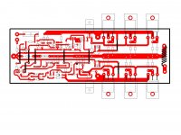
it looks excelent i thing but my friend you are in the wrong thread this is the bipolar version of quasi ...
also your pcb is double leyer .... in a double leyer you can do miracles regarding space but you cant be realy sure what is going to happen before you test the board regarding induction and capacitance between traces and leyers ...
though what i ve seen so far looks very neat and well organized
good work my friend
Hi Sakis here is the schematic... for bipolar we have to add devices in PCB
VI Limiter is from Big Power PA Amp, to design this Quais PCB was a lot of nights work
If you have ideas to improve") or find faults... send me message
or find faults... send me message
I think about to add in forthcoming QUASI design electronic turn on and off delay without relay and crowbar for DC protect
Crowbar for DC protect is no problem, have finished but electronic turn on and off delay without relay,.. I have headache and need assistance
Have PA amp schematic from 80s with Quasi Bipolar output devices, electronic turn on and off delay without relay and Crowbar for DC protect,
Later Models have Bipolar output devices and changes in VI limiter and turn on and off delay
I think we should copy and add this in our QUASI Amp too, how do you think about this ?
VI Limiter is from Big Power PA Amp, to design this Quais PCB was a lot of nights work
If you have ideas to improve
or find faults... send me messageI think about to add in forthcoming QUASI design electronic turn on and off delay without relay and crowbar for DC protect
Crowbar for DC protect is no problem, have finished but electronic turn on and off delay without relay,.. I have headache and need assistance
Have PA amp schematic from 80s with Quasi Bipolar output devices, electronic turn on and off delay without relay and Crowbar for DC protect,
Later Models have Bipolar output devices and changes in VI limiter and turn on and off delay
I think we should copy and add this in our QUASI Amp too, how do you think about this ?
Attachments
Last edited:
quasi's threads ( i mean first of all quasi as a person and secondly as a designer) are threads to discuss the quasi amps ....this amplifier may be a quasi as a topology but still its not what CON originally designed
so modifying somebody elses circuit is a diferent story
As about the thread is Con's decision what to do
as about the schematic and your pcb i have to say that looks like a pretty well made job on the other hand though i have to be very skeptic regarding an untested device and/or schematic .
bipolar quasi i ve made 4 so far working like hell in small PA application and i can really tell you that they are performers !!! ( given as a fact the simplicity of the design and the cost of it )
it will take time , testing , many to construct , many to use and many to abuse , to make a final thing ....
i congratulate about your work but beyond that allow me to move on the safe side
happy regards sakis
( there is a chance your circuit to be even better than Con's the thing is that its not tested .... simulated may be, but that is not enough )
I moved my web site
Greetings,
I changed ISP's recently and had to quickly move my web site. It is located here; Home (Quasi's DIY Audio Site)
It is being re-built so please be patient.
Cheers
Quasi
Greetings,
I changed ISP's recently and had to quickly move my web site. It is located here; Home (Quasi's DIY Audio Site)
It is being re-built so please be patient.
Cheers
Quasi
Hi,
I didn't yet proceed to BOQ construction.Once reason is i want monoblock configuration but I haven't right tranny to acheave that. Beside I have in stock 2 pieces of 300VA 2x25VAC and 4 units of 22.000µF/40V. Did anyone see any objection to drive BOQ with PSU that will give me about 34/35V DC rail. If no objection will BOQ need value changes? I will maintain initial 8 output device for whole chanel. This DC rail will give me about 60W at 8R (more than enough for my home use)and no stress against low impedance and tortured phase shift speakers....
Regards Marc
i actually see this as an overkill ....trully a waste of output transitors .... but yes will happiliy drive any load .... also with so many outs there could be an otion to beef up the bias so you get closer to class A operation ....
con will have to place his opinion for that ...
con will have to place his opinion for that ...
I agree that will be a "little bit" overkill, but i have lust to redrawn pcb since it take me a lot of time....and other side i have enough output device in stock that i can "waste" trough this way. Other advantage is the possibility to upgrade later rail VDC to higher amount if it usefull. The main advantage for in this configuration is the amp immunity to low impedance/strong phase shift speaker....
Marc
Marc
Look up Borbely, he only uses FETs and recommends a minimum of 500mA output bias AND recommends each output device is biased to >=100mA.I have in stock 2 pieces of 300VA 2x25VAC and 4 units of 22.000µF/40V. Did anyone see any objection to drive BOQ with PSU that will give me about 34/35V DC rail. .........I will maintain initial 8 output device for whole chanel.
+-35Vdc & 500mA bias dissipates 35W. That is a pretty big heatsink.
He uses 5pair for a 50W into 8ohm amp, DC50servo.
Look up Borbely, he only uses FETs and recommends a minimum of 500mA output bias AND recommends each output device is biased to >=100mA.
+-35Vdc & 500mA bias dissipates 35W. That is a pretty big heatsink.
He uses 5pair for a 50W into 8ohm amp, DC50servo.
Borberly use 3 mosfet pair in DC to be able to drive 4Ohms speakers. Dissipation will not be a problem to since heatsink i have are big enough.
Marc
Hi,
I didn't yet proceed to BOQ construction.Once reason is i want monoblock configuration but I haven't right tranny to acheave that. Beside I have in stock 2 pieces of 300VA 2x25VAC and 4 units of 22.000µF/40V. Did anyone see any objection to drive BOQ with PSU that will give me about 34/35V DC rail. If no objection will BOQ need value changes? I will maintain initial 8 output device for whole chanel. This DC rail will give me about 60W at 8R (more than enough for my home use)and no stress against low impedance and tortured phase shift speakers....
Regards Marc
Hi Marc,
The amp will work but you will need to remove R7 and replace with a wire link. This will provide sufficient voltage for the ccs transistor T4 to work. You may also have trouble adjusting VR2 for sufficient bias current so you may need to replace R13 with a 680 ohm resistor.
For such low voltages you could omit half the output transistors.
Cheers
Quasi
- Status
- This old topic is closed. If you want to reopen this topic, contact a moderator using the "Report Post" button.
- Home
- Amplifiers
- Solid State
- Brother of Quasi