And the last evolution, the one i will use after putting together on study board all my need and possibilities. Suitable home place is an important criteria and i don't want to exced 24x25x34cm (WxHxD), use of a maximum parts i have in stock is a another.
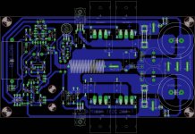
The main project turn on 500VA Rcore 2x36Vac, 8xMur3020WT for rectification, 32.000µF/63V smoothing caps per Voltage rail, 6x MJL3281A paired output devices. Each output device emitter resitor will consist on a little pcboard that support 4x 1R8 1W 1% metal resistors in parallel
Marc
The main project turn on 500VA Rcore 2x36Vac, 8xMur3020WT for rectification, 32.000µF/63V smoothing caps per Voltage rail, 6x MJL3281A paired output devices. Each output device emitter resitor will consist on a little pcboard that support 4x 1R8 1W 1% metal resistors in parallel
Marc
Attachments
Last edited:
...
Each output device emitter resitor will consist on a little pcboard that support 4x 1R8 1W 1% metal resistors in parallel
...
Nice idea!

Nice idea!
That's my way to avoid difficulties to find locally 5W 0r22 non inductive resistors
Marc
They are easily found on ebay @ about 0.625 / pcs. These should be OK quality wise.
Yes but since i don(t have paypal account, it's difficult to purchase...and due the Fake proliferation i lost habit to look at ebay and prefer local purchase.
Marc
Last edited:
Do this emitter resistors or source resistors in output transistors need to be non-inductive?
This is the requirement i always read.
Marc
Lot's of chance.
Do you know the consequences?
Of course I know
what are the chances can you elaborate?
Hi Idefixes,
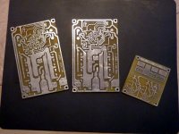
The boards that you suggested are single sided. How do you solder the ones that has to go to the heatsink? Sorry for my stupidity. This has been bothering me for a long time and I still can't figure out how this can be done. Or can anyone tell me how? Do you have to use some rig for this? Thank you for your time.
The boards that you suggested are single sided. How do you solder the ones that has to go to the heatsink? Sorry for my stupidity. This has been bothering me for a long time and I still can't figure out how this can be done. Or can anyone tell me how? Do you have to use some rig for this? Thank you for your time.
Hi Idefixes,
The boards that you suggested are single sided. How do you solder the ones that has to go to the heatsink? Sorry for my stupidity. This has been bothering me for a long time and I still can't figure out how this can be done. Or can anyone tell me how? Do you have to use some rig for this? Thank you for your time.
Hi, I will screw board and transistors on a (plastic, wood....) sheet that was large cuted in the center (under board) and so let acces to parts solder pad.
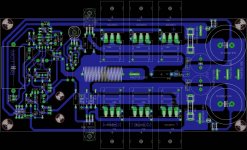
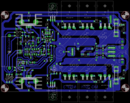
My Nbip board has big evolution on routing job last few monthes.BD139 will be screw direct on MJL3281. see attached (PCB : 100x160mm standart board)
Attachments
Last edited:
None.................what are the chances can you elaborate?
Hi Idefixes,
One minor point , you had one end of R21 connected to the fused -ve rail. Does it matter if I had that end connected to the un-fused -ve rail? Any affect on the operation (normal operation or in case of failure)?
Thanks
BP
When you do so -Ve fuse as no protection effect on case of faillure.
Marc
- Status
- This old topic is closed. If you want to reopen this topic, contact a moderator using the "Report Post" button.
- Home
- Amplifiers
- Solid State
- Brother of Quasi