LOL, Thanks for your opinions everyone. Sounds like i've still got a lot of work to do with this amp. If i can get it to sound any better than it already does i'll be in heaven. Some seem to think it sounds rarther harsh or bad but i assure you it doesn't. I think i'll make a start on the filter, wind myself some air cores. I really want to stick with the triangle design, just somthing about self oscillating designs i don't like. I think its an unknown or out of controll frequency thing that puts me off. I'm taking all your comments on board though, its very interesting to see some conflicting views and ideas, long may we all experiment!
P.S looking forward to you posting your amp design classD4sure
")
Good luck all who build!
Mad.P
P.S looking forward to you posting your amp design classD4sure
Good luck all who build!
Mad.P
Hi,
The design.. got posted long ago, I just posted the pics of how it looks today, taken off the breadboard. They're in the "Development of a "reference" class D starting point" thread.
I'd recommend further research into self oscillating class d, frequency modulation isn't much of a problem and can even be beneficial.
Regards,
Chris
Do you mean this one? or the latter?classd4sure said:I disagree about them having to be more complex and certainly disagree with them being slow. Simple discrete drivers are plenty fast for the speed we're interested in, at any power level's we're interested in.
Attachments
The latter one
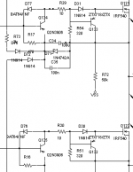
It's cut from the file DIY_UCD.png downloaded somewhere this forum. This circuit is rather simple enough. If it is fast enough, I would consider to use it (maybe on the next of the N+P version)
Does the 2N3906 runs into satuation? It needs 200ns to recover if it does satuates.
This will do a great harm since it slowes down the turn off of MOSFET -- to prevent shoot-through, fast OFF and slow ON is appreciated.
The schottky diode between base and collector could prevent satuation in a certain extent, but I don't know the actual perfomance -- could the MOSFET turn off in 20 ns since the input signal changes?
Also, the pull-down emitter follower is a bit weak to pull a current of 1A and turn the MOSFET off in tens of nanoseconds. Current gain of transistors drop hardly at high frequency / high current.
Maybe the ZETEX transistors in the graph is capable of the job, but I couldn't get any. What I could get is 3904/3906, 5401/5551, 2222 and some asian products: 8050/8550 (1.5A 80MHz), 772/882(3A 80MHz). The latter two ones are dedicated to linear amplification instead of fast switching.
Attachments
Re: The latter one
Hi,
What do you mean on the next N + P version? It's a dual N channel driver.
I can't even comment on that first circuit, personally I don't feel it's an option. I know we discussed it before.
The second schematic I recognise as being one of mine. It's not my invention. It's a standard N channel driver circuit, which I've shown before on the forum as such, and have also shown the variation of it for a complimentary output stage, it uses the same number of transistors as it does for dual N channel. The Baker clamp may be unique to Bruno in this application, otherwise it's standard stuff.
I can't prove the circuit's worth to you, research it, simulate it, build it. You have some valide points of concern, some not so valide, sounds like a plan of action to me.
I'll give you some hints though. I'm not using the Zetex part in the actual circuit either, it's all 2N3906, the Zetex part has worse Ft, and still would not be a problem, it does handle higher current than a 3906, but that's still not the reason it's there. It would be preferred both because of it's higher current capability, and mainly because of the lower Vce sat.
You could use gold dopped BJT's if you're heavily paranoid about saturation, all you need is a well designed Baker clamp, nothing saturates.
IC's are limiting in alot of ways. You always have to design the circuit around them. Aside from that if you find a good one and want to try it, sure, why not. I prefer to stick with trying to master discretes, and I'll be far less limited for it.
Also, when I did blow a mosfet, I may have had to change 1 two cent transistor, not a 10$ IC. That's a bonus.
Clarification:
"Simple discrete drivers are plenty fast for the speed we're interested in, at any power level's we're interested in."
When I said that, I meant any power level we'd be interested in (sanely) building on a protoboard.
Regards,
Chris
Kenshin said:It's cut from the file DIY_UCD.png downloaded somewhere this forum. This circuit is rather simple enough. If it is fast enough, I would consider to use it (maybe on the next of the N+P version)
Does the 2N3906 runs into satuation? It needs 200ns to recover if it does satuates.
This will do a great harm since it slowes down the turn off of MOSFET -- to prevent shoot-through, fast OFF and slow ON is appreciated.
The schottky diode between base and collector could prevent satuation in a certain extent, but I don't know the actual perfomance -- could the MOSFET turn off in 20 ns since the input signal changes?
Also, the pull-down emitter follower is a bit weak to pull a current of 1A and turn the MOSFET off in tens of nanoseconds. Current gain of transistors drop hardly at high frequency / high current.
Maybe the ZETEX transistors in the graph is capable of the job, but I couldn't get any. What I could get is 3904/3906, 5401/5551, 2222 and some asian products: 8050/8550 (1.5A 80MHz), 772/882(3A 80MHz). The latter two ones are dedicated to linear amplification instead of fast switching.
Hi,
What do you mean on the next N + P version? It's a dual N channel driver.
I can't even comment on that first circuit, personally I don't feel it's an option. I know we discussed it before.
The second schematic I recognise as being one of mine. It's not my invention. It's a standard N channel driver circuit, which I've shown before on the forum as such, and have also shown the variation of it for a complimentary output stage, it uses the same number of transistors as it does for dual N channel. The Baker clamp may be unique to Bruno in this application, otherwise it's standard stuff.
I can't prove the circuit's worth to you, research it, simulate it, build it. You have some valide points of concern, some not so valide, sounds like a plan of action to me.
I'll give you some hints though. I'm not using the Zetex part in the actual circuit either, it's all 2N3906, the Zetex part has worse Ft, and still would not be a problem, it does handle higher current than a 3906, but that's still not the reason it's there. It would be preferred both because of it's higher current capability, and mainly because of the lower Vce sat.
You could use gold dopped BJT's if you're heavily paranoid about saturation, all you need is a well designed Baker clamp, nothing saturates.
IC's are limiting in alot of ways. You always have to design the circuit around them. Aside from that if you find a good one and want to try it, sure, why not. I prefer to stick with trying to master discretes, and I'll be far less limited for it.
Also, when I did blow a mosfet, I may have had to change 1 two cent transistor, not a 10$ IC. That's a bonus.
Clarification:
"Simple discrete drivers are plenty fast for the speed we're interested in, at any power level's we're interested in."
When I said that, I meant any power level we'd be interested in (sanely) building on a protoboard.
Regards,
Chris
Hi all,
I've been fiddling with my amp trying to make some improvments. However i seem to have hit a brick wall. First i tried to improve the filter by lowering the inductance to 24uH. When powered up in open loop mode the amp worked as befor except for a nasty 2v sinewave shown on the scope at my switching frequency. This is to be expected as the filter now approaches the switching frequency cut off. I was prepared to give it a go but the sinewave seemed to interfere quite badly with NFB to such an extent that is made it impossible to stablise the amp or hush it up. Also there must be an alteration in the phase as the amp was very keep to enter oscillation. I tried to remedy this by taking feedback from pre-filter on the bridge. This was useless and even worse caused startup problems. Thinking about it i don't understand how you can successfully use feedback from the bridge as it is just a raw PWM wave and looks nothing like the sine wave it is being matched with. Interestingly though when applied in very small quantites it appeared to completley null any audio signal entering the amp. Strange? Maybe i need to filter the pre-filter signal befor i can use it? Whatever the case the old inductor is back in for now as that gives me about 100mV of RF ripple and the only nasty thing on the output is switching transients but they are so quick they don't appear to bother anything. Anyone know any good articles about using feedback in a class D amp i can read up on? Somebody mentioned earlyer in the thread that i should use faster op-amps and comparaters. I can't see any advantage in doing this as the amp works fine as it is and putting a faster op-amp in the design could actually cause more harm than good if it is so fast it starts to amplify transients. It may also contribute to HF oscillation. Hmm, maybe the lack of speed has somthing to do with the pre-filter feedback not working?? I can see a long journey ahead of me..... Chris i've looked at your amp thread and its a nice peice of work.. Far more advanced than this thing LOL. I must admit though i don't wish my amp to become over-complicated as it's already going to be a pretty large beast when you think of all thats required to go into it to create a stereo version. It's gotta be better than an Acoustic Soloutions effort though even as is ( i have some of their stuff. In my own opinion its rubbish ).
I would appreciate any feedback on the feedback
Mad.P
Hi,
You're beginning to see why we said "you were lucky" lol.
Yeah control theory isn't my strong suite. You likely do need to filter the square wave before using it as feedback, but I'm not going to tell you thats' going to solve it.
Filter cut off, what do you want? Sub amp? For full range 30Khz is lots, and the oscillating frequency should be 10X that or more. I'd push it up to 350~500kHz.
I think the second you go with anything other than a self oscillating design, it's already over complicated. They're alot simpler and far more robust. Worth researching anyway.
Regards,
Chris
Re: Re: The latter one
It's "on the next of the N + P version", after I finish the recent one, I'll probably do a dual N channel one.
About satuation: I didn't used Baker clamp in my BJT version, and met with satuation trouble, so I'm worrying about satuation.
ps:I'm still wondering to improve the BJT version -- can't get MOSFET suitable for low power level.
classd4sure said:
Hi,
What do you mean on the next N + P version? It's a dual N channel driver.
Regards,
Chris
It's "on the next of the N + P version", after I finish the recent one, I'll probably do a dual N channel one.
About satuation: I didn't used Baker clamp in my BJT version, and met with satuation trouble, so I'm worrying about satuation.
ps:I'm still wondering to improve the BJT version -- can't get MOSFET suitable for low power level.
You would have to integrate the output signal before you could use it for NFB. But then you would have to integarte the input signal as well, otherwise you would end up with a very strange frequency response.
Now the rules of integral calculus come to your rescue: You don't need to integrate both and then sum them at the feedback point, you can sum them first and integrate both at once. So you would just need one summing- (miller-) integrator. You could even use the same integrator to form the triangle out of your rectangular (as Sony did). But I think seperate generation of triangle might also have advantages.
Regards
Chalres
phase_accurate said:...You could even use the same integrator to form the triangle out of your rectangular (as Sony did). But I think seperate generation of triangle might also have advantages.
Regards
Chalres
sony thing=pseudo self oscillating/not really??
EDIT: Just back to add a sentence to that reaction.
What you mentioned of sony seems to imply self oscillating and yet rules it out by saying a seperatly generated triangle might have advantages.
It sounds like it might have had some of the advantages of a self oscillating amp though.
Charles are you still kicking around the idea of a paper on feedback/control theory?
Regards,
Chris
Re: Re: Re: The latter one
You can use BJT's if you're really stuck but they're far from efficient, at low power it should be OK. If you can get your hands on old computer SMPS, Monitors... anything else you can think of, you'll probably find enough MOSFETs to play with.
I see no reason you can't use a high power mosfet in a low power circuit, I am.
Samples are good too if you can get them.
If you can't get Shottky diodes for your Baker clamps, let me know when you get there, I have a two diode alternative for you, seems to work just fine.
Regards,
Chris
Kenshin said:
It's "on the next of the N + P version", after I finish the recent one, I'll probably do a dual N channel one.
About satuation: I didn't used Baker clamp in my BJT version, and met with satuation trouble, so I'm worrying about satuation.
ps:I'm still wondering to improve the BJT version -- can't get MOSFET suitable for low power level.
You can use BJT's if you're really stuck but they're far from efficient, at low power it should be OK. If you can get your hands on old computer SMPS, Monitors... anything else you can think of, you'll probably find enough MOSFETs to play with.
I see no reason you can't use a high power mosfet in a low power circuit, I am.
Samples are good too if you can get them.
If you can't get Shottky diodes for your Baker clamps, let me know when you get there, I have a two diode alternative for you, seems to work just fine.
Regards,
Chris
You all seem very secretive on here but i appreciate the hints. I think your right when people say i had a very lucky start. I think my first attempt is fairly close to the ideal for this design as it stands. I'm determined to sort out a better feedback control though so i can fix my filter. It's nice that the wads of inductance flatten out the final sinewave but it must be wasting power and causing loss of som of my top end. Even though the amp sounds nice and clear i have a feeling inaudiable top end maybe lacking, not a prob for my ears but bad for the design. I think the air core idea should be used as this should stop heat being generated in the core. I can't see the coil heating up by its self in free air.
Heres an interesting point, looking at the schematics i provided early in the thread, if you remove the op-amp and run the feedback through a 10nF cap you can inject it directly into the triangle wave generator to produce a really silent very nice sounding amp. There are obvious issues with this especially at start up and i wouldn't recomend using this for a serious design but its clear and the bass is really reinforced. Sounds lovely to the ears but i don't think it will be very linear ( sounds like sombody has pressed the loudness button ). I endevour to find out why........
Regards,
Mad.P
Heres an interesting point, looking at the schematics i provided early in the thread, if you remove the op-amp and run the feedback through a 10nF cap you can inject it directly into the triangle wave generator to produce a really silent very nice sounding amp.
This way you did indeed implement an "el cheapo" version of the feedback scheme I was talking of: A summing integrator.
The downside is that this integrator has only damping and no gain so you can achieve only low feedback factors. The triangle will not be very linear either. But simple RC circuits will struggle much less when fed signals like rectangulars.
An example for an integrator-based class-d amp you will find under:
http://www.diyaudio.com/forums/attachment.php?s=&postid=194684&stamp=1056096858
Regards
Charles
Hi all,
I've been fiddling with the feedback circuit again trying to realise my desire to apply more and add a self biasing circuit to make the amp safe for higher outputs. I'm having no luck with pre-filter feedback at all, and can't seem to find any other ways to improve my post filter feedback. rummaging around the net to see which method 'sounds best' there are all sorts of conflicting views. Some say pre, others say post. Has anyone actually heard the difference on a single amp being modified to do both? If so what type won? That in mind i've also looked into summing intergration methods of modulation instead of plain PWM. I might give this a try as i will be able to use feedback from the bridge to drive the integrater, however i will have to raise the clock frequency to at least double what it is now. Not a problem, just hope the DTI does not bust me for wiping out the medium wave band!
Every one on here thinks that the self oscillating amp is the way to go. Why is this? Do they sound better, because if they do i would rarther find out sooner than after i've finished an inferior design. Tell me your opinions on this, especially if you have compared the two. I feel like a customer in a shop not knowing what to buy. If its subjective listening influencing things then fair enough, i'll just have to make up my own mind. But if there are definate flaws in one of these types of amp i want to know befor i build one. I feel the design i have done so far is a good one and it sounds better than the typical commercial units i have had. However i can't belive for one moment that this is as far as i can go, as if i just happend to build a good amp for my first attempt at classD. My last classA design took ages and saw many a burnt finger hot plugging components ( not to mention a burnt wallet when the electricity bill arrived LOL ) I've discoverd there is somthing rarther magical and enchanting about classD so on goes the search for more in terms of sonic perfection, and belive me i want to go all the way
Take care,
Mad.P
Me again,
Just thought i'd comment that on a large proportion of amp designs i've been looking at the feedback is taken from a point in between two output filters that are wired in series as one. Is this to keep interference from getting into the feedback circuit from a source external to the amplifier? Hmmmm........
Mad.P
Hi,
As far as I'm concerned self oscillating is the way to go.
Simply because it's self correcting.
It incorporates the delay of the output stage for instance, output coil (optional and preferred)...
Back in the day when they said class d was only good for sub amps, they weren't incorporating the filter coil in the feedback loop and so you had an uncontrolled load and frequency response that varied with it, along with filter non linearities.
There are other ways of correcting for the output stage delay but I find self oscillating is the easiest. It's also highly robust.
Then you can do away with a triangle generator, dont' have to worry about it being perfectly linear which it never is anyway, or how to cleanly route it around the circuit while maintaining linearity.
Jitter becomes a thing of the past.
There's ways of addressing all of the above in clocked class d amps but non so simple, and so it tends to reduce component count a great deal.
Oh and, all the class d amps that are worth their salt are self oscillating. ICEpower, UCD, Mueta (not that it exists) the list goes on.
Worth looking into.
It's not that we're secretive or not willing to share but it wouldn't do you any favors if all the answers were handed out.
Regards,
Chris
Hi all,
After going down the path of carrier design i have not really looked at the self oscilating design in any great depth. I now intend on doing so and now i'm starting to think about how this concept actually works. As far as i figure, the output stage stays the same but the signal is fed back into the input stages in such a way as to cause oscillation ( just as in feedback ). Any delays in the switching will therfore become unimportant as long as they are reasonabley equal ( high to low, low to high ). With no input signal the amp should in theory just flick from low to high with a ratio of 50% at a frequency determined by the total switching delay. My output stage is quite fast and clean switching. It goes from low to high in 20n/s, add to that the dead time delay of approx 100n/s, anougher 20n/s for the MAX driver, and say 20n/s for the rest of the junk and that gives a total of 160n/s. That means at idle i reakon that it should tick at approx 3.125MHz. That is alarmingly fast. I hope there is some way of controlling the frequency. Usally fast is good but things might start to get a bit silly here, the inductor is going to be working really hard to filter all that out. I hope i have got the theory correct so far. I think i'll put the present amp to one side and start this amp on its own board using low power and some small ZVP4424 fets ( thats how i started with the present design ) I'll make sure it is stable on the scope and run it on a small speaker till i'm confident ( you can get an amazing 5 to 10 watts out of these little e-types befor they cook ). It's getting late now so i think i'll sleep on the input stage as i cant quite map it out in my mind just yet
If i wake up with no answers i'll have to score the net at work tommoz and see if i can find an explaination. The constuction will begin after work tommoz so feel free in the mean time to shout STOP if you think i'm gonna melt a nice peice of breadboard LOL.
This may sound like a strange way of doing things but this is how i usally work, 6 days of thinking something up in my head, then when it works in my mind i usally throw it together and have it tested and running in an hour or so on the bread board. ( Unlike my coding were i type first and think later ( if it don't work )) I have been known to do the odd etch or two as well
Night all yawwnnn...
Mad.P
nitrate said:Hi all,
After going down the path of carrier design i have not really looked at the self oscilating design in any great depth. I now intend on doing so and now i'm starting to think about how this concept actually works. As far as i figure, the output stage stays the same but the signal is fed back into the input stages in such a way as to cause oscillation ( just as in feedback ). Any delays in the switching will therfore become unimportant as long as they are reasonabley equal ( high to low, low to high ). With no input signal the amp should in theory just flick from low to high with a ratio of 50% at a frequency determined by the total switching delay. My output stage is quite fast and clean switching. It goes from low to high in 20n/s, add to that the dead time delay of approx 100n/s, anougher 20n/s for the MAX driver, and say 20n/s for the rest of the junk and that gives a total of 160n/s. That means at idle i reakon that it should tick at approx 3.125MHz. That is alarmingly fast. I hope there is some way of controlling the frequency. Usally fast is good but things might start to get a bit silly here, the inductor is going to be working really hard to filter all that out. I hope i have got the theory correct so far. I think i'll put the present amp to one side and start this amp on its own board using low power and some small ZVP4424 fets ( thats how i started with the present design ) I'll make sure it is stable on the scope and run it on a small speaker till i'm confident ( you can get an amazing 5 to 10 watts out of these little e-types befor they cook ). It's getting late now so i think i'll sleep on the input stage as i cant quite map it out in my mind just yet
If i wake up with no answers i'll have to score the net at work tommoz and see if i can find an explaination. The constuction will begin after work tommoz so feel free in the mean time to shout STOP if you think i'm gonna melt a nice peice of breadboard LOL.
This may sound like a strange way of doing things but this is how i usally work, 6 days of thinking something up in my head, then when it works in my mind i usally throw it together and have it tested and running in an hour or so on the bread board. ( Unlike my coding were i type first and think later ( if it don't work )) I have been known to do the odd etch or two as well
Night all yawwnnn...
Mad.P
Yep you caught on nicely, now I look forward to seeing what you come up with, well worth burning a few protoboards for.
Speaking of which do you simulate them in your head as well? Tesla supposedly did that with his inventions, mechanical anyway, no doubt he dreamt of electron flow as well.
Why don't you try a few ideas on a simulator, draw it out as you go and you can try all kinds of variations quickly and easily, kind of.
Regards,
Chris
- Status
- This old topic is closed. If you want to reopen this topic, contact a moderator using the "Report Post" button.
- Home
- Amplifiers
- Class D
- Breadboard Class D!!