This amplifier topology is a self oscillating design so it will not work if you take the logic part and blend with something else.
It relys on the pre feedback to oscillate, cut that and oscillation stops.
I am noteven sure if my mod will actually work, the original had discrete gate drivers but i remember nitrate mentioning that he tried with gate driver ic´s with good results, he dident mention which tho.
I don´t think your signal was a real pwm signal as you dident have the rest of the amplifier in place, with the logic section only there is no oscillation, so your "pwm" signal was just the comparator triggering on every peak in the music signal that was above the trigger threshold of the comparator.
Hello,
My logic part is not a part of your self oscillating design. Indeed it is composed with a trig generator (333 KHz 0,8 V pk-pk) a oa (preamp, ao with unity gain and level shifting) and a comparator (LM393N). I think I have a real PWM signal. I just plug a LC filter on PWM signal (from output of comparator and a 74HC14 gate for best rise time) and I can heard some music. Now I will use your design for power amp part with UCC37?? mos driver and IRF520/540 mos.
Many thanks for your repply!
Hello,
I learn about self oscillating design but I keep (for the moment) the trig gen and comparator design. I tried your power stage design Tekko with ic driver UCC3722/21 and it works (but my proto sounds really bad :/).
Now I try power stage design from Nitrate (the first one posted page 3 with ic driver max626). This stage is a half bridge design with P and N mosfet. I think something goes wrong with my proto because irf9530 and 520 ran very hot very quickly and there is no sound from the speaker connected in. I understant that mosfet are short cuted despite gates signal seems to be good.
Indeed for the IRF9530 I get the pwm modulation (0-15V because my drivers are 15V supplied) + a DC voltage offset (+50V). For the irf520 I get the same with a negative DC voltage (-50V). I think this is good. I measure these two signals with a scope and I get a delay (delay is set up by resistor in // with diode before the last 74hc14 gates for each channel), this means to be ok. So I think maybe my mosfet are down?
How to quickly know if mosfet are right? I measure resistance between source and drain of each (with a digital multimeter) and there is 0 Ohm for each. I think this is not good because a N channel may have 0 Ohm but the P channel may have a big resistance (maybe I confuse with N and P), haven't they?
Last strange things is the resistor (10R) in line with output of gate driver of the up channel (with 9530P), before the small cap was always destroyed when there is no power supply (for me +/- 50V)
My full system :
Design from Nitrate 'MadAmp' which is viewable on page 3 of this topik. Ic drivers : UCC3721 (inversed). Power supply +-50V (80VA I guess, scraped supply from old bass amp) and power supply for ic drivers +15V but only 10VA. Zener diode for level shifting after cap and resistor in line with output from IC driver : 12V (I guess these must be 15V because I supply my IC with 15V)
I will try design which works before design my owm.
Many thanks for your help
Indeed 9530 is slower than 530 (N channel are faster than P I guess).
I destroyed all my mosfets (next time I will take care of electrostatic discharges). In order to have a only N channels half bridge it is necessary to build a pump charge (with bootstrap design), isn't it? The pump charge is needed because high side driver must be supplied with a higher voltage than bridge's voltage (positive branch), isn't it?
I would apologize about my silly questions, I'm just a beginner
Hello boyZ
I'm just loggin in to see how things are in this forum. You will be glad to know my amp is stored away safley and still comes out for the occasional demo when freinds come by. I'll soon be in a position to re-cindle and hopefully finish this project, until then have fun ppl, and keep building!
P.S i'm glad to see my design lived on for so long after i went, it's almost touching lol

Back in a month or two.. see yaZ!
I'm just loggin in to see how things are in this forum. You will be glad to know my amp is stored away safley and still comes out for the occasional demo when freinds come by. I'll soon be in a position to re-cindle and hopefully finish this project, until then have fun ppl, and keep building!
P.S i'm glad to see my design lived on for so long after i went, it's almost touching lol
Back in a month or two.. see yaZ!
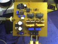
I've been toying with class D recently, so here s my try.
http://vec7or.com/img/VSCD/VSCD1.1.GIF
Runs at ~30kHz, filter at ~5.4kHz, single supply, signal from ground. No feedback whatsoever.
For now its rattling some furniture by supplying the sub, sounds relatively clean, just that filter has a little hump in responce and it is excited by the carrier.
I also have one question, the cores I'm using are 100uH 5A, pale yellow toroids and they run pretty warm, is that because of too low/high switching frequency ?
Attachments
If the core size are OD=.942", Height=.375", and around 50 turns, then this core have white line else on the yellow compound, it's material #26 from Micrometals (T95-26B). So it's hardly suitable for class D at all, try material #2 (red toroids) or any type of ferrite even. BTW, check this out http://www.ferroxcube.com/appl/info/class D audio amplifier.pdf
To use two comparators instead single+XOR or invertor, pretty bad idea, lm319: 8mV voltage offset +InputOffsetCurrent+InputBiasCurrent, it'll give additional nonlinearity.
To use two comparators instead single+XOR or invertor, pretty bad idea, lm319: 8mV voltage offset +InputOffsetCurrent+InputBiasCurrent, it'll give additional nonlinearity.
The cores are pale yellow color, coloring is uniform, no bands whatsoever.
I know about the comparator, I just wanted to make it real simple and cheap. Next version will use LT1016 or LM319 or something fast.
I also plan to use gapped cores from Epcos, RMxx series.
This is just a cheap and dirty version, and it works.
I know about the comparator, I just wanted to make it real simple and cheap. Next version will use LT1016 or LM319 or something fast.
I also plan to use gapped cores from Epcos, RMxx series.
This is just a cheap and dirty version, and it works.
I'm Back!!
Hey All,
I'm back!! LOL... Time for a new amp design now i think, I have a wad of monster FETs so i'll build a new amp, a carrier i think as i'm fed up with the self osc designs blowing up. Hmm... start at 300KHz, 35V RMS output for 75W into 8R / 150 into 4R, then after getting it stable let it grow....lol
See yaZ soon
Mad.P
Re: I'm Back!!
Hi nitrate, new breadboard?
Yeah! it seems a good project for home use...
nitrate said:Hey All,
I'm back!!
Hi nitrate, new breadboard?
nitrate said:
300KHz, 35V RMS output for 75W into 8R / 150 into 4R
Yeah! it seems a good project for home use...
Lol,
Yeh.. new breadboard amp..... got proto up and running, just need to clear up some whisleing noises in the background ( sounds like RF ) may have to take it off the bread board, might plump for some veroboard LOL. I'll post some schematics and photos n stuff as soon as i work out my protection circuitry.... This is one amp i'm determined to make bomb proof. In fact just stop it from destroying the outputs like my previous amps did would be a vast improvment LOL. So far so good tho.... no casualties yet
LaterZZ
Mad.P
LOL
I knew i'd get comments about those 4148 diodes, i had a party last night, me and a few mates came back to my place after pub closing hours and we played music till 4am the next day. The amp was flat out all that time but the 4148's survived! bless them
Anyway just to put your minds at rest i'm gonna replace them now with some ultrafast high current diodes, namely MUR460RL. I have a a pack of these laying around and they should be ideal.
Some have noticed my feedback coming after the filter, this i have chosen to do to help eliminate the dodgeyness of the filter, it also helps to keep emf pulses out of the error amp stage. Belive me or not on this design the sound is much better this way, if i try taking the feedback from the bridge the high notes sound 'scratchy' and the scope shows high frequency interferenc on the output waveform. Maybe if i sort my inductor there will be less energy kicking around to cause this interference. Either way i like the idea of total global feedback, not just a shortcut from the bridge.
P channel fets are rare to say the least and changing my design to an all N channel is a wise move. I don't like the idea of bootstraping to create yet anougher power supply to drive the top fet, but i know its the right way to go, should mean i can use almost any high speed fet in the design.... i've already got hold of suitable driver chips from National Semis. Feels like i'm relying too on chip solutions though if i go down that route... Hmmm Besides i like maxim products because of their gaurantee of non obsolesence!
Somebody asked how i came up with the design, well i got reading this forum one day at work and i decided that i wanted to try class D for myself. I looked up on the net a description of class D amps so i knew what made them tick, then just sat down with a lump of breadboard and a scope and literally built one. I'm an electronic design engineer you see so thats what i do for a living, just sit down and build prototypes for to answer customers problems. Anyway i started by building a 275KHz clock. Origanally i used a 4093 i.c but the cmos familly aint fast enough. It ticked o.k but the square was not very square on the scope so i was forced to use high speed TTL family ( 74*** ) This also required the addition of a 5v supply. After the clock i added the next stage, the triangle. Easily done by way of anougher gate to buffer the clock then charge/discharge a cap from the output of the gate. I went to great lengths tweaking the values of the cap/resistor in order to obtain the purest triangle i could. When i was satified with the wave i then added the comparater, and a variable voltage divider. If all is well i should be getting a 50% pwm wave out the comparater. This checked out o.k so i decided to try sticking that into a p/n fet bridge across a 5v supply. This worked well so i tried stuffing a simple filter on the output ( actually the one i still use ) and hook up a speaker just to see what it sounded like. It was supprisingly good. I was using tiny e-line package fets to test it. After a succesfull test run i went to a bigger supply ( 12v ) and created a level shift circuit on the high side. This worked but the fets were getting quite hot even at idle. I found the drive was starting to get sloppy, Square was no longer square from the comparater so i tried squareing it up by buffering with anougher logic gate. This worked a bit but it eventually blew the logic. This is when i decided to use the maxim driver. Things were back up and running, but the fets were still a little warm. I just thought this was down to the small fets. Continued on next post....
Amazing description of your design process: the problems you encountered and how you solved them !
Kudos !
More people should do that.
Where are you now with your class D amp design ?
Long time no see...
Lol,
Glad you enjoyed the thread. Its been a long time since this thread was active. Gotta say that little amp was a really nice sounding one, even tho it didn't comform to convensional design it did the job just fine. I eventually got the rail up to 40V and that's as far as that project went. After that i started to create N channel mosfet monsters using the usuall split rails and bootstraped supplies but i still have a place in my heart for this little amp. I might re-create two channels of it and stuff it in a box as a gift for my dad. He doesnt need the kind of volume i demand and this little amp always had a smooth sound, rarther like that of my tube/fet hybrids. A good amp for newbies to experiment with the building blocks of classD too i think
Enjoy.. feel free to build and modify, take this thread too if you wish
 Long live the 'Do'ers doers, not just thinkers!!
Lol,
Glad you enjoyed the thread. Its been a long time since this thread was active. Gotta say that little amp was a really nice sounding one, even tho it didn't comform to convensional design it did the job just fine. I eventually got the rail up to 40V and that's as far as that project went. After that i started to create N channel mosfet monsters using the usuall split rails and bootstraped supplies but i still have a place in my heart for this little amp. I might re-create two channels of it and stuff it in a box as a gift for my dad. He doesnt need the kind of volume i demand and this little amp always had a smooth sound, rarther like that of my tube/fet hybrids. A good amp for newbies to experiment with the building blocks of classD too i think
Enjoy.. feel free to build and modify, take this thread too if you wish
Long live the 'Do'ers doers, not just thinkers!!Hey Nitrate,
Thank you for posting up your project! I guess it goes back a few years now, but I found this thread very interesting. Exactly - 'long live the do'ers'! I find there is a certain amount of discouragement in the class D forum, though it may not be intentional. There are those in the industry, or at an advanced level who are all about making the smallest, most efficient amplifier possible. And that's great, but I find their explanations usually come with a tone and style that is almost intended to drive off experimentation.
Anyway, all that to say I think it's really cool that you just went ahead and put together an idea on a breadboard and started playing around. And you had success too! I find this thread refreshingly encouraging for beginners, and exciting!
Jim
Last edited:
- Status
- This old topic is closed. If you want to reopen this topic, contact a moderator using the "Report Post" button.
- Home
- Amplifiers
- Class D
- Breadboard Class D!!