Valery,
This is very interesting..... but I must say that I have problems understanding the words a little, but it's complex indeed, well expressed too, but it's my damaged brain.
Nonetheless, I use this layout in one of my amps and have found indeed that it is incredibly quiet, amazingly stable, and DC to light FR. I suspect Damir uses this in his amps too, which have no global feedback so this much be dead linear. A variant of this, though without the diode, is the Lender topology. I think yours is superior - I have demonstrated this to myself!
Thanks for joining the thread!
Hugh
Is that across each transistor or pair? I bias EF bipolar outputs at 15 - 26mV across each Re, so with those 0.22 ohm ones you are looking at about 68 - 118mA.
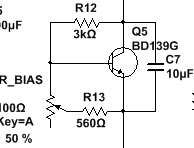
Edit: you might find it tough to get enough compliance with 3k in the upper arm and a 100 ohm trimmer in the lower leg. Replace that 3k with 1 - 1.5k or replace the trimmer with 200 ohm. Then recalc.
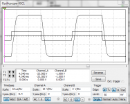
Those square waves don't look to too good from here. Defeat the RF filter in the sim and run it again. If no major improvement then play around with the compensation values.
Edit: you might find it tough to get enough compliance with 3k in the upper arm and a 100 ohm trimmer in the lower leg. Replace that 3k with 1 - 1.5k or replace the trimmer with 200 ohm. Then recalc.
Those square waves don't look to too good from here. Defeat the RF filter in the sim and run it again. If no major improvement then play around with the compensation values.
Last edited:
Ranchu32 - It's the bias servo. I can try your suggestion. The servo will be mounted to the heatsink and not the transistor for what that's worth.
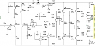
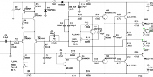
I've been trying to clean up this schematic and get my callout numbers in order.
Should Q6 have a small capacitor from emitter to collector? I have that in one of my other amps but don't remember why I put it there.
EDIT - 1.5k, 220r+100r does 2.43-423ma. 67.5ma at midpoint on the trimmer.
I've been trying to clean up this schematic and get my callout numbers in order.
Should Q6 have a small capacitor from emitter to collector? I have that in one of my other amps but don't remember why I put it there.
EDIT - 1.5k, 220r+100r does 2.43-423ma. 67.5ma at midpoint on the trimmer.
Attachments
Last edited:
Don't put any cap across Q6's E - C.
Q5 is a horrible choice. Use something like a KSC1845 or even a 2N5551 if you haven't any better.
C6 is far too small for this design, the output devices and the operating points. The ULGF is 4MHz!! I don't care what the sim says it will blow up in real life. Set it to 150p and work down from there.
You've upset the input pair's balance by placing 23k ohm at the non-inverting input and only 22k ohm at the other input. Is this what you wanted to do?
Member
Joined 2009
Paid Member
Hi Hugh, Gareth, Christian and All - A few thoughts on the topic, if I may.
If we can eliminate Cdom we're ahead of the game in terms of loading on the LTP - since Cdom is multiplied by the Miller Effect it's drag on the LTP becomes dominant before we reach 20kHz. I've no experience of using a shunt load at the VAS, D. Self and others have noted that it's somewhat poisonous to the VAS and that Cdom does have the benefit of providing local feedback around the VAS which improves it's linearity.
Nice catch. With a two-device VAS the dc current draw from the LTP will be much smaller than with the single VAS so some kind of current balance is much more achievable if the devices are matched and these resistors balanced.You've upset the input pair's balance by placing 23k ohm at the non-inverting input and only 22k ohm at the other input. Is this what you wanted to do?
Last edited:
Don't put any cap across Q6's E - C.
Q5 is a horrible choice. Use something like a KSC1845 or even a 2N5551 if you haven't any better.
C6 is far too small for this design, the output devices and the operating points. The ULGF is 4MHz!! I don't care what the sim says it will blow up in real life. Set it to 150p and work down from there.
You've upset the input pair's balance by placing 23k ohm at the non-inverting input and only 22k ohm at the other input. Is this what you wanted to do?
Thank you for that. Yes, the BDxxx VAS was chosen because there was nothing following it. When I added the additional transistor, I didn't consider the load it would remove from the LTP, as Bigun just mentioned.
Was it you, AKSA who mentioned the bottom resistor in the LTP was typically 2x the top resistor? With a 2n5551 as a VAS, per Ranchu32's suggestion, the lower resistor is very close to 2x the top resistor.
Distortion is significantly lower! Holy cow! 0.008%!?
Back to tests...
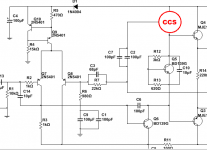
Why not do both? Build a constant current source using a PNP transistor and appropriate bias components, AND bootstrap the CCS's positive supply terminal using a capacitor connected to the output. Now you get both greater-than-supply output capability, AND true constant current.
Why not do both? Build a constant current source using a PNP transistor and appropriate bias components, AND bootstrap the CCS's positive supply terminal using a capacitor connected to the output. Now you get both greater-than-supply output capability, AND true constant current.
I don't follow you. Put the CCS where?
I don't follow you. Put the CCS where?
Put it between the positive supply rail and the top end of the VBE multiplier / bias spreader. The bottom end of the VBE multiplier goes to the NPN VAS transistor's collector. Figure attached. C2 is the bootstrap capacitor.
_
Attachments
Last edited:
I imagine so. I myself avoid the 2T shunt feedback current source like Q1+Q2 in post#53; I find it has a tendency to oscillate unless base stopper resistors are included. So I generally prefer to use the 5-component current source instead: 2 diodes, 2 resistors, 1 PNP transistor.
Then once you've got a constant current source you need to design circuitry that lets it work in unison with the bootstrap capacitor.
Then once you've got a constant current source you need to design circuitry that lets it work in unison with the bootstrap capacitor.
I myself avoid the 2T shunt feedback current source like Q1+Q2 in post#53; I find it has a tendency to oscillate unless base stopper resistors are included.
People keep saying this but I've never had a problem personally. I normally use a TO-23 sense transistor fixed to the board underside in very close proximity to the pass device. I don't even bother with the base stop any more; the only precaution taken is a 100n - 1u X7R cap from rail to ground, and I only do that if the trace is more than a couple of inches from the nearest decoupler.
- Status
- This old topic is closed. If you want to reopen this topic, contact a moderator using the "Report Post" button.
- Home
- Amplifiers
- Solid State
- Bootstrapped amps. DX/Aksa/RCA/etc...