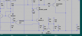
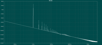
Found this so called baxandall pair VAS from one of Ostripper's work. Harmonics peak is quite interesting...worth investigating I think
Sa muli,
Albert
Hi Albert,
This is actually a cool combination of Baxandall super-pair and Hawksford cascode - a joint development of myself and Ostripper - see my hybrid TubSuMo front-end >HERE<
First appeared in >THIS THREAD<
This VAS arrangement provides rather high open loop linearity and excellent clipping behavior. However, I went further, moving in the direction of the current-driven VAS - see the latest development >HERE<
")
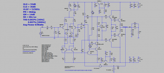
Updated schematic (minus 2 resistors) is >HERE<
Let me know if you will have questions
Cheers,
Valery
Add provision for resistors to be added in series with C4 and C15
You may not need them, links instead.
Add more locations for local supply rail decoupling.
Add resistor in the horizontal leg between the top of R23 and the collector of Q11, D.Self's Vbe error correcting.
Add resistor+diodes between Signal Return and Power ground/Speaker Return.
Add pads to Q17 to allow the 2sa to be changed to a BC5xx type, if you find the 2sa cannot perform in near saturation.
Make provision for all capacitors to have multi pin pitch options.
Try to get all your polar caps facing in the same direction.
Add 4 protection diodes (1n4002 or higher) from supply rails to output and from supply rails to Power Zero volts.
Last edited:
Add provision for resistors to be added in series with C4 and C15
You may not need them, links instead.
Add more locations for local supply rail decoupling.
Add resistor in the horizontal leg between the top of R23 and the collector of Q11, D.Self's Vbe error correcting.
Add resistor+diodes between Signal Return and Power ground/Speaker Return.
Add pads to Q17 to allow the 2sa to be changed to a BC5xx type, if you find the 2sa cannot perform in near saturation.
Make provision for all capacitors to have multi pin pitch options.
Try to get all your polar caps facing in the same direction.
Add 4 protection diodes (1n4002 or higher) from supply rails to output and from supply rails to Power Zero volts.
Very good suggestions AndrewT,
adding a series resistor to C4 and a small VBE correcting resistor...sounds like a necessity
I know the risk involved in the input stage, the first time I powered to such CFP input the thing oscillated by itself. I got dc VOLTS in the output.. 
Interesting thread, I was reminded by an old amp build that I made based on AKAI design. The schematic was traced by an old mentor from the original board, I drafted it in CADware. I do remember that I made some resistor values in the bias circuit because I was using newer devices, (and yes one terminal of the trimpot is left hanging in the pcb) for a low power amp SQ is very good. (Astron was a local manufacturer/distributor.)
Hi Abetir,
Do you have a pcb design of this akai astron amp. I'm planning to build this good sounding quasi amp.I like the bass response of this amp.
Thanks,
Gorex
- Status
- This old topic is closed. If you want to reopen this topic, contact a moderator using the "Report Post" button.
- Home
- Amplifiers
- Solid State
- Bootstrapped amps. DX/Aksa/RCA/etc...