The direction of three arrows showing currents in figure 8 are of fundamental importance.
Ig = Ie + If
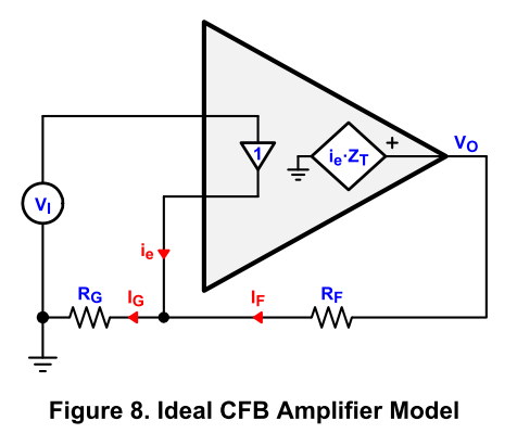
That is a good illustration of the CFA, and the cited article is a good read. Note also that their Figure 5 is quite similar to the simplified schematic of a CFA power amplifier I showed in my book: A unity-gain input buffer with a fairly conventional VAS and output stage, where the feedback current flows into the output of the unity gain buffer and through the buffer to drive the VAS.
As mentioned in the article, one of the important distinguishing features of the CFA is that, to first order, the loop gain does not change when the closed loop gain is changed by changing the value of the feedback shunt resistor, here Rg (it DOES change if the closed loop gain is changed by changing the value of the feedback resistor).
This property can be very valuable in applications where the gain must be changed for whatever reason, including equalization. For instance, if you need to equalize the HF loss of a long twisted pair (which tends to increase as the square root of f), you put a network in the shunt leg of the feedback network of a CFA. As the impedance of that network decreases with increasing frequency, the gain of the equalizer thus formed increases, but the loop gain of the system does not change.
In a dedicated audio power amplifier, the gain is usually fixed, so this particular property of a CFA does not bring much to the table.
The CFA also has some advantages at high frequencies insofar as the path that the feedback sees around the loop. In particular, starting from the output, the feedback sees what looks like a common-base input stage in the form of the input buffer. As far as the feedback sees it, this is potentially faster than the common-emitter-like input differential pair of a VFA, as long as the input impedance that the buffer sees at high frequencies is relatively low. The feedback thus ends up seeing, as it traverses the loop, is a common base stage (IPS) followed by a common emitter stage (VAS) followed by a common collector stage (OPS).
Cheers,
Bob
I hear a dull noise coming from the lactating cachinnating quadruped near the permanent habitation of the Raptors
Thanks Bob for all the extremely hard work that it took to produce a Masterpiece of a very difficult subject, writing a book is hard, but making the subject of the book understandable to most people is Outstanding.
Thanks Bob for all the extremely hard work that it took to produce a Masterpiece of a very difficult subject, writing a book is hard, but making the subject of the book understandable to most people is Outstanding.
@Krisfr and @syn08 is this still about Bob's book (rhetorical question Rhetorical question - Wikipedia)
That is a good illustration of the CFA, and the cited article is a good read. Note also that their Figure 5 is quite similar to the simplified schematic of a CFA power amplifier I showed in my book: A unity-gain input buffer with a fairly conventional VAS and output stage, where the feedback current flows into the output of the unity gain buffer and through the buffer to drive the VAS.
As mentioned in the article, one of the important distinguishing features of the CFA is that, to first order, the loop gain does not change when the closed loop gain is changed by changing the value of the feedback shunt resistor, here Rg (it DOES change if the closed loop gain is changed by changing the value of the feedback resistor).
This property can be very valuable in applications where the gain must be changed for whatever reason, including equalization. For instance, if you need to equalize the HF loss of a long twisted pair (which tends to increase as the square root of f), you put a network in the shunt leg of the feedback network of a CFA. As the impedance of that network decreases with increasing frequency, the gain of the equalizer thus formed increases, but the loop gain of the system does not change.
In a dedicated audio power amplifier, the gain is usually fixed, so this particular property of a CFA does not bring much to the table.
The CFA also has some advantages at high frequencies insofar as the path that the feedback sees around the loop. In particular, starting from the output, the feedback sees what looks like a common-base input stage in the form of the input buffer. As far as the feedback sees it, this is potentially faster than the common-emitter-like input differential pair of a VFA, as long as the input impedance that the buffer sees at high frequencies is relatively low. The feedback thus ends up seeing, as it traverses the loop, is a common base stage (IPS) followed by a common emitter stage (VAS) followed by a common collector stage (OPS).
Cheers,
Bob
Thanks for that Bob. The reason I suggested some more detail in a possible future edition is that CFAs enjoy (?) a lot of attention in audio, some manufacturers even touting 'this is a CFA design' as a quality mark. That in itself would be, I think, enough reason to treat it more than just in passing.
Again, no criticism to the book, just a suggestion.
Jan
The reason I suggested some more detail in a possible future edition is that CFAs enjoy (?) a lot of attention in audio, some manufacturers even touting 'this is a CFA design' as a quality mark. That in itself would be, I think, enough reason to treat it more than just in passing.
So you think a technical book should expand and therefore endorse what appears to be a fashion topic? Hmmm... Otherwise, one may wonder why it took so much time (with a few exception, like the Accuphase products, the famous 40 years) to discover this "quality mark"?
“...which is exactly what I’m trying to convey. Of course, I can hear loud and clear the noise coming from the audio CFA fan club”
When will you stop making an issue over CFA’s? If some people want to design with CFA let them be. Have you considered that if you denigrate CFA and promote VFA you are a member of the VFA fan club? How is that better than a CFA fan club member? It’s a nonsense.
Your attitude and obsession on this issue is truly tiresome and adds no value to any discussion.
As for the ‘noise’ on this issue, may I suggest it’s coming from one source only : you
So you think a technical book should expand and therefore endorse what appears to be a fashion topic? Hmmm... Otherwise, one may wonder why it took so much time (with a few exception, like the Accuphase products, the famous 40 years) to discover this "quality mark"?
Maybe you can not design CFA amplifier better than VFA amplifier?
Some of member here proved they can design CFA amplifier with good specification, example: Dadod.
And then you said, they sound same before you try to listen?
This is DIY, everyone free to try everything and make comparison.
So you think a technical book should expand and therefore endorse what appears to be a fashion topic?
There's hundreds, possibly 1000's of topologies and concepts. Solid state, tube, balanced, single ended, triples, duals, LTP, CFA, VFA, Darlington, quasi-symnmetrical, the list goes on and on. All in the designers toolbox.
You just want to outlaw one of them because apparently for some reason it doesn't fit your personal theology.
Take off your blinders.
Jan
I've built both types - from 15W class A to 200W+ (CFA and VFA) class AB. As discussed many times (or tried to) as the OLG is raised (and thus the LG for any typical audio amplifier) of a CFA so that it approaches that of a typical VFA, you end up having an amplifier whose outward behaviour becomes indistinguishable from that of a VFA. You cannot get around the fT limit of the output devices and the phase shifts that accumulate with more active stages and you therefore have to design the compensation accordingly.
Personally, I don't see any 'magical' properties in either topology and you can design an build very high performance amps either way. What is clear though is that if you want very wide loop bandwidths (which some practitioners like - not saying it is the holy grail but just a design preference) then moderate loop gain CFA's are the way to go. An example of this approach is the class A sx-Amp. But, the distortion is quite high because of the low loop gain. The kx-Amp raises the loop gain and as a result the loop bandwidth ends up getting reduced as a side effect of the necessary compensation - but the distortion is very low (few 10's of ppm)
I have not designed and built a VFA since the e-Amp (2012). I just enjoy designing and building CFA's - that's my preference.
As mentioned in the article, one of the important distinguishing features of the CFA is that, to first order, the loop gain does not change when the closed loop gain is changed by changing the value of the feedback shunt resistor, here Rg (it DOES change if the closed loop gain is changed by changing the value of the feedback resistor).
this is also true for MIC compensated VFA
This is a different mechanism LKA. In a high loop gain CFA and a high loop gain VFA you can use TPC or OIC or one of the other more modern compensation techniques to have a flat, wideband, loop gain. Look at dadod's amplifier to see this. The open loop corner frequency of these high gain CFA's is LOW - just like a VFA.
In a moderate loop gain CFA, you are not getting a flat, wide band loop gain because of the compensation - it just is very wide with low phase shift (c.f. low OLG) through the amplifier so you only need light compensation to ensure the output stage pole falls below the ULGF in magnitude terms. This is exactly the case with the sx-Amp were the loop gain bandwidth is 60 kHz.
In a moderate loop gain CFA, you are not getting a flat, wide band loop gain because of the compensation - it just is very wide with low phase shift (c.f. low OLG) through the amplifier so you only need light compensation to ensure the output stage pole falls below the ULGF in magnitude terms. This is exactly the case with the sx-Amp were the loop gain bandwidth is 60 kHz.
Last edited:
As mentioned in the article, one of the important distinguishing features of the CFA is that, to first order, the loop gain does not change when the closed loop gain is changed by changing the value of the feedback shunt resistor, here Rg (it DOES change if the closed loop gain is changed by changing the value of the feedback resistor).
Cheers,
Bob
This is something I have difficulty to understand. You (and others) showed that there's no appreciable signal current going through Rg, it being shunted by the very low buffer output impedance.
How then can it determine the closed loop gain?
Jan
This is a different mechanism LKA. In a high loop gain CFA and a high loop gain VFA you can use TPC or OIC or one of the other more modern compensation techniques to have a flat, wideband, loop gain. Look at dadod's amplifier to see this. The open loop corner frequency of these high gain CFA's is LOW - just like a VFA.
In a moderate loop gain CFA, you are not getting a flat, wide band loop gain because of the compensation - it just is very wide with low phase shift (c.f. low OLG) through the amplifier so you only need light compensation to ensure the output stage pole falls below the ULGF in magnitude terms. This is exactly the case with the sx-Amp were the loop gain bandwidth is 60 kHz.
maybe different mechanism but the result is similar
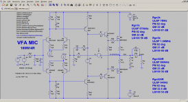
VFA MIC schematic
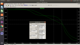
LG Rg=1k
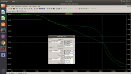
LG Rg=2k
Attachments
The buffer is a voltage source of low impedance. It does not shunt Rg, it delivers current into Rg in parallel with current from Rf.This is something I have difficulty to understand. You (and others) showed that there's no appreciable signal current going through Rg, it being shunted by the very low buffer output impedance.
You just want to outlaw one of them because apparently for some reason it doesn't fit your personal theology.
Take off your blinders.
Do I? If you think so, then you conveniently misrepresent what I was saying all along. Why are you doing this is a mystery to me.
BTW: YAP Front End
The buffer is a voltage source of low impedance. It does not shunt Rg, it delivers current into Rg in parallel with current from Rf.
Yes, I know your views on this. Its a bit like the chicken and egg thing. What comes first, Vout or the error current from the buffer.
In your view, it is the latter, and I can see the logic.
I wonder what Bob says to this?
Jan
- Home
- Amplifiers
- Solid State
- Bob Cordell's Power amplifier book