Agreed. Indeed, adding risk to an amplifier design (e.g., of parasitic burst oscillations) just to get lower distortion numbers by going to very high ULGF is not wise. This philosophy also applies to pushing hard at one aspect of performance at the possible cost of others.
Examples of this might be pushing for extremely low noise or extremely high slew rate, or extremely high DF at high frequencies.
Cheers,
Bob
Hi Bob,
You think that the risk to increase ULGF is not wise. I tried to show you one built power amp a few post back (200W) with the ULGF of 5.1 MHz but you ignored it.
This one is 100W version, and I used it every day with no hint of instability, and its ULGF is over 5 MHz too. Because it's quite log thread here is the link: http://www.diyaudio.com/forums/solid-state/243481-200w-mosfet-cfa-amp-92.html#post4580555. Those two power amps are with VMOSFET OPS, but I simulated the version with bipolar OPS with ULGF of 2.5 MHz and simulation shows even better result.http://www.diyaudio.com/forums/solid-state/253039-unique-cfa-120-230w-amp-25.html#post4665073
This kind of challenge is for young people (I am 72 with young soul), why you are afraid of it?
I have your book and I love it, but really why not add CFA in next edition?
best wishes
Damir
It's more common to use a bandwidth of 22 kHz (theoretical max possible frequency from a 16 bit 44kHz compact disc) in noise calculations for audio, see Self 6th ed p. 151 list item 2.
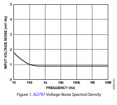
However it's fairly easy to achieve < 4nV/rtHz in a power amp with unbalanced inputs, at the cost of other specifications. "Merely" build a noninverting input stage running at a gain of +14dB (5X) from an AD797 opamp whose input voltage noise is < 1nV/rtHz and whose bandwidth is 22 MHz at a gain of 5. Live with a low input impedance of 500 ohms, which you achieve using a 100 ohm input bias resistor (and 100R feedback resistor) plus 5X bootstrap. Fit a DC servo to deal with any DC offsets. Connect your bog standard 10nV/rtHz Blameless power amp to the AD797 output and jiggle the compensation capacitor to make the cascade stable with good phase margin. Done.
Total input voltage noise is the RMS sum the individual noise sources: (10 nV / 5x gain) for the Blameless, (1 nV) for the AD797, and (1.29 nV) for each of the 100R resistors. The RMS sum works out to be: 2.89 nV/rtHz. And it was easy.
BUT: you have an unbalanced amplifier: forget XLR inputs. You were probably forced to reduce its open loop bandwidth to maybe 80% of the unadorned Blameless bandwidth, to accommodate the extra phase lag from the AD797. You had to cough up an extra $10.50 for the AD797 and then you had to provide ±15V power supplies to drive it. And the finished amplifier has a 500 ohm input impedance so you can't possible drive it with a "passive preamp".
Attachments
Hi Bob:
Thanks for the update.
Seems to me that you made a good compromise.
")
In my opinion, CFA needs a book of it's own.
Maybe even something along the style of Jim Williams' "Analog Circuit Design: Art, Science and Personalities" from several years ago. It would be pretty cool to have such a book with contributions from a number of experts and/or successful amp designers.
OK, OK, I'll wake up now ...
mlloyd1
Thanks for the update.
Seems to me that you made a good compromise.
In my opinion, CFA needs a book of it's own.
Maybe even something along the style of Jim Williams' "Analog Circuit Design: Art, Science and Personalities" from several years ago. It would be pretty cool to have such a book with contributions from a number of experts and/or successful amp designers.
OK, OK, I'll wake up now ...
mlloyd1
Hi Richard,
Not a serious treatise. Time and space are running out. Much more space is being devoted to the following subjects, some of which are completely new chapters:
Building an amplifier - detailed construction and testing of an amplifier
Noise
full complementary JFET input stages
Advanced forms of NFB compensation
Output stages
Switching power supplies
Professional power amplifiers
There are other numerous additions and updates, but these are the big pieces.
Cheers,
Bob
Hi Bob,
You think that the risk to increase ULGF is not wise. I tried to show you one built power amp a few post back (200W) with the ULGF of 5.1 MHz but you ignored it.
This kind of challenge is for young people (I am 72 with young soul), why you are afraid of it?
I have your book and I love it, but really why not add CFA in next edition?
best wishes
Damir
Some comments related to CFA seems to be extrapolation from experience with VFA. Not from experience with CFA. The existing books by Self and Bob are good summaries of the many details found in various places for VFA all put together into a single book(s).
The CFA details are primarily discussed in professional journals and research papers and academic papers. Today's students in EE need to know SOTA circuitry. CFA is that SOTA area and most fast, high freq signal IC's use it. However, it works exceptionally well for audio, also.
I would suggest the potential for any osc of a CFA is lower due to parasitic L and C's due to the low Z's used for high speed. Or it can be with proper selection of devices. That has been my experience with CFA and why I say it is easier to make to be stable if you design a current mode operated circuitry.
If it leads to ultra low distortion and very high speed SR and wide bandwidth and low noise beyond the minimum needed for audio.... so be it.
THx-RNMarsh
Stability of CFA PAmp...... When I received Dadod's loaded pcb i powered and tested it with clip lead jumpers for everything... to load, groundings, PS leads... long lead wires all over the place..... no oscillation or instability. Nor when same lash-up drove QUAD ESL for loads.
THD+N P into 4R

THD+N vs Freq 50W/8R

THD+N vs Freq 200W/8R

A few examples, only. I will double check these because the results are close to limit of this old SYS ONE dual-domain Audio Precision used at factory.
THx-RNMarsh
THD+N P into 4R
THD+N vs Freq 50W/8R
THD+N vs Freq 200W/8R
A few examples, only. I will double check these because the results are close to limit of this old SYS ONE dual-domain Audio Precision used at factory.
THx-RNMarsh
Last edited:
D. Self does a pretty good job of pointing out that balanced inputs ruin your chances of achieving 4 nV/rtHz input voltage noise. Since balanced inputs are absolutely required in the year of our lord 2016,
This is why before I could attempt my first amplifier build I was obliged to tackle the challenge of implementing Self's ultra-low-noise balanced to single-ended input stage (SSAD 2nd Ed. chapter 18).** My Theta Digital Casablanca IV preamp/DAC/controller only has balanced outputs.
As I went through my first amp assembly I was surprised (appalled?) at all the hoops that had to be jumped through to ensure the "ground" reference remained clean. First I had to go from balanced to single-ended, then star on star, carefully route that ground wire etc etc. Bruno Putzey's article the G Word began to resonate more loudly each day. Why not discard the ground reference altogether and go fully balanced? As a newbie to this hobby I'm wondering why the topic isn't discussed more often with designs presented...
Perhaps it is unnecessary when one becomes skilled in the dark art of star grounds.
** I stopped at the quad LM4562 (LME49740) and didn't venture into AD797 territory
Last edited:
I'll pass it to factory people. I received them all turned 90 degree side-ways. I changed them all to horizontal. But when uploading and attaching to DIY page, one stayed as I had it and two didnt. On my computer, they are all horizontal. THx-RNMarsh
Last edited:
The CFA details are primarily discussed in professional journals and research papers and academic papers. Today's students in EE need to know SOTA circuitry.
Hilarious that this was written by someone who refuses to use surface mount components, even though they are State Of The Art.
THx-RNMarsh
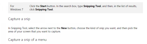
I think he suggested to use screen shots rather than photos from a camera. The screen shots can be cut out and rotated and saved and send, with better resolution as well. I think it would save you time and frustration and make better pictures. I learned that very fast when I started editing for Linear Audio!
Jan
Just tried it with an arbitrary screen open, see attached. Easy as pie, and much better images.
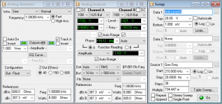
Even AP screens come out well (sorry, didn't have a test handy).
Jan
Even AP screens come out well (sorry, didn't have a test handy).
Jan
Attachments
Last edited:
I would suggest the potential for any osc of a CFA is lower due to parasitic L and C's due to the low Z's used for high speed. Or it can be with proper selection of devices. That has been my experience with CFA and why I say it is easier to make to be stable if you design a current mode operated circuitry.
TTYH, as usual. CFAs are overly sensitive to any capacitance across the feedback resistor, and are also usually worse to drive capacitive loads. The former makes actually CFAs harder to compensate (and the layout more critical), since the lag compensation (yes, a technical concept that I'm sure you know about) technique doesn't apply. You should see how snipping a SMD CFA op amp pin 1 removes 0.1pF of parasitics and stops some HF oscillation.
Your experience with audio CFAs has nothing to do with the CFA that the industry successfully uses in wideband applications. At least because at the closed loop gains common in audio (20...30dB) any relevant CFA specific properties are long gone. And please don't come up with the high slew rate argument, it is not specific to CFAs.
P.S. CFA was SOTA before I was an itch in my dad's pants.
New to amp construction!
Hello, my name is Ron
I recently began research on class A and class AB amplifier construction. Im not that far into this and have been using an app to make basic schematics. I know the basics of how some circuits work to the point that i have made schematics on my app sjow success. havent made any until I'm comfident i know they will work. I've seen the amp camp kits and considered that my start until a friend of mine (kevin) turned me to diyaudio because a few legends reside here, two of them being Mr. Pass and Mr. Curl. I would really love to learn all I can about less is more amp construction so maybe one day i can make my own. I have many ideas I have taken from other technology and any help or advice. I would also like to find the book that Mr. Bob Cordell had just authored. kind regards from a new builder, Ron Miller
Wanna back up these claims with theory or preferably evidence? Oh .. and on PAs rather than Zillion GHz chips and applications.CFAs are overly sensitive to any capacitance across the feedback resistor, and are also usually worse to drive capacitive loads. The former makes actually CFAs harder to compensate (and the layout more critical), since the lag compensation (yes, a technical concept that I'm sure you know about) technique doesn't apply.
The 'lag compensation' you speak of refers only to a particular type of compensation ... favoured by Bob & JLH but not many others.
One could consider the 'modern' VFA as a CFA with an extra EF(s) introduced to buffer the feedback .. so would be LESS stable as it has another rolloff .. albeit a VHF one.
BTW, I'm a fan of so called 'VFAs' except for very specific applications.
translation?TTYH, as usual.
Last edited:
Hi Bob,
You think that the risk to increase ULGF is not wise. I tried to show you one built power amp a few post back (200W) with the ULGF of 5.1 MHz but you ignored it.
This one is 100W version, and I used it every day with no hint of instability, and its ULGF is over 5 MHz too. Because it's quite log thread here is the link: http://www.diyaudio.com/forums/solid-state/243481-200w-mosfet-cfa-amp-92.html#post4580555. Those two power amps are with VMOSFET OPS, but I simulated the version with bipolar OPS with ULGF of 2.5 MHz and simulation shows even better result.http://www.diyaudio.com/forums/solid-state/253039-unique-cfa-120-230w-amp-25.html#post4665073
This kind of challenge is for young people (I am 72 with young soul), why you are afraid of it?
I have your book and I love it, but really why not add CFA in next edition?
best wishes
Damir
Hi Damir,
I apologize for not responding to that post of your amplifier. It looks like a nice design. A 5MHz ULGF is impressive, although under some conditions I think it is easier to achieve with Vertical MOSFETs than with BJT with a given amplifier topology.
Cheers,
Bob
The 'lag compensation' you speak of refers only to a particular type of compensation ... favoured by Bob & JLH but not many others.
I'm confused. What particular type of lag compensation are you referring to above that I favor and others don't? I don't generally favor lag compensation in the first place; I generally favor Miller compensation and some variants thereof, like TPC, TMC and MIC. Can you clarify?
Cheers,
Bob
Wanna back up these claims with theory or preferably evidence? Oh .. and on PAs rather than Zillion GHz chips and applications.
The 'lag compensation' you speak of refers only to a particular type of compensation ... favoured by Bob & JLH but not many others.
- http://www.ti.com/lit/an/sloa021a/sloa021a.pdf part 8 and part 9.
- Audio amplifiers are not CFAs, they may only share the classic CFA circuit topology. As already mentioned, because of the rather large closed loop gains, the core CFA properties are lost. Therefore, your request for a PA example is moot. You may think of a CFA as asymptotically merging with VFAs (in terms of transfer function), as the closed loop gain increases. Again, high slew rate is NOT a specific CFA property, but a particular circuit feature (current on demand) which can be implemented in VFAs as well.
- Sorry for the typo, that would be lead (not lag) compensation being bad for CFAs. The same TI white paper covers this topic.
That's it, I'm not going to start this stupid debate again.
P.S. Talking Through Your Hat.
One could consider the 'modern' VFA as a CFA with an extra EF(s) introduced to buffer the feedback .. so would be LESS stable as it has another rolloff .. albeit a VHF one.
Not much basis for this statement. Fully complimentary processes have enabled a lot of different topologies compartmentalizing them like this serves nothing. For instance the double-diamond input stage with bridging resistor has lots of Vbe's and since the Is of pnp vs npn rarely matches there are lots of opportunities for offset, drift, and noise so these amps tend to be used in high speed lower precision applications because they have slew on demand as a side benefit. Since they have a constant input transconductance and GBW product irrespective of feedback network they are VFA's, period.
Same holds true for VFA's with slew enhancement but in this case the discontinuity in the large signal transfer function makes them useless if you care about THD. The goal here is not continuous time applications but enhancing settling time to a final value and sampling the output.
Last edited:
Hilarious that this was written by someone who refuses to use surface mount components, even though they are State Of The Art.
what? .... that has nothing to do with cfa in a popular format/book. But apparently it has been redefined to be always a VFA, also. Maybe there is no such thing as internal current mode operation? .... Anyway,
In my order of priority-- building sh_t is last and building it the hardest way is below that. I would prefer to go out and lay in the dirt under my car and drain the oil and filter.
-rnm
Last edited:
- You may think of a CFA as asymptotically merging with VFAs (in terms of transfer function), as the closed loop gain increases.
I can sort of agree with this. As a special condition. Just include it in the book.
As far as the TI paper is concerned...... bad writing. Covered better and more thoroughly in books and academic papers. Current mode operation as opposed to voltage mode of control and operation really is different.... regardless of the out-come.
THx-RNMarsh
Last edited:
- Home
- Amplifiers
- Solid State
- Bob Cordell's Power amplifier book