I understand what Waly is saying, in his own characteristic way. Slew rate margin doesn't always have a direct relationship with distortion.
You have to separate the concept of slew rate which has an accepted definition of the limit of the rate of change in the amplifiers output voltage, and the large signal open-loop response of the amplifier. That is the input voltage (and sometimes current) vs. frequency and amplitude that makes the output be exactly what you want it to be. Backwards analysis is powerful, assume the output is perfect and work back to determine what the input has to be, it flips cause and effect around and gives a different insight on things.
I'm working on a vanilla topology (single LTP, single ended VAS, triple EF OPS) voltage feedback audio amplifier with ±42V supplies -- 80 watts/channel. At the moment its ratio of (Miller_compensation_cap / IPS_bias_current) is 3.9 picofarads per milliamp. At that setting the amp is quite stable and well behaved, even in clipping, at least in simulation.
Solomon's formula from his ancient opamp tutorial (Equation 17) predicts a slew rate of 256 V/us , and I'm seeing about 210 V/us in simulation. The clipping misbehavior preventers are stealing some of the slew current but I don't mind. So that's 210/42 = 5 volts per microsecond per volt of supply. Is this slew rate good enough or should I keep trying for more?
Solomon's formula from his ancient opamp tutorial (Equation 17) predicts a slew rate of 256 V/us , and I'm seeing about 210 V/us in simulation. The clipping misbehavior preventers are stealing some of the slew current but I don't mind. So that's 210/42 = 5 volts per microsecond per volt of supply. Is this slew rate good enough or should I keep trying for more?
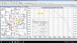
Compensation used in 200W CFA
Current on demand is important quality of CFA but compensation is most important here.
When I started this CFA compensation it was first with TPC:
upper leg: C7+R22+C6
lower leg: C14+R30+C9
and R1 to get two pole compensation around enhanced VAS.
PM not good enough.
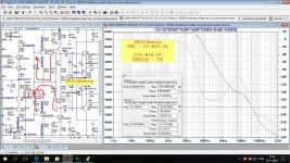
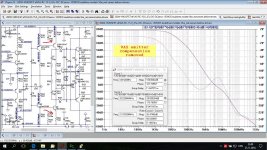
After that Chary compensation added with C8 from the output to the TPC R1, actually to the enhanced VAS inputs and it improved the Phase Margin greatly.
The VAS emitter compensation added to improve the Loop Gain at higher frequencies. It increases ULGF to 5.5 MHz.
A crude calculation made before fine simulation tuning.
I hope this can help to explain the compensation used and it was quite easy with this CFA.
Damir
Current on demand is important quality of CFA but compensation is most important here.
When I started this CFA compensation it was first with TPC:
upper leg: C7+R22+C6
lower leg: C14+R30+C9
and R1 to get two pole compensation around enhanced VAS.
PM not good enough.
After that Chary compensation added with C8 from the output to the TPC R1, actually to the enhanced VAS inputs and it improved the Phase Margin greatly.
The VAS emitter compensation added to improve the Loop Gain at higher frequencies. It increases ULGF to 5.5 MHz.
A crude calculation made before fine simulation tuning.
I hope this can help to explain the compensation used and it was quite easy with this CFA.
Damir
Attachments
No, current on demand is a feature of a certain circuit topology, which happens to be the most common for CFAs. Current on demand exists in pure VFAs, see the Stochino amp and it's mega-slew rate.
Current on demand is important quality of CFA
Richard are you implying it is NOT 1V/V (or twice) for a CFA?
Let's do this in a democratic way, I propose 4V/V. Anybody concur? Wait, make that 6V/V to be on the safe side, doesn't matter audio signals don't slew faster than 0.1V/V (not even that).
No, current on demand is a feature of a certain circuit topology, which happens to be the most common for CFAs. Current on demand exists in pure VFAs, see the Stochino amp and it's mega-slew rate.
At least until it catches fire. Must find out what failed on it. Couldn't tell you how good it is as nothing to reference against, but the remaining unit plays music.
At least until it catches fire. Must find out what failed on it. Couldn't tell you how good it is as nothing to reference against, but the remaining unit plays music.
I doubt you need almost unlimited slew on demand like some of the complimentary bridged amps have. One of my co-workers has also retired, his last amp will be 40,000V/usec with THD specd out to 2GHz.
wow, that's big bragging rights.
")
how would you even measure THD reliably around 2GHz anyways?
i do miss access to the fancy test gear, but i'm not sorry I got out of telecom a while back ...
mlloyd1
how would you even measure THD reliably around 2GHz anyways?
i do miss access to the fancy test gear, but i'm not sorry I got out of telecom a while back ...
mlloyd1
his last amp will be 40,000V/usec with THD specd out to 2GHz.
CFAs are overly sensitive to any capacitance across the feedback resistor, and are also usually worse to drive capacitive loads. The former makes actually CFAs harder to compensate (and the layout more critical), since the lag compensation (yes, a technical concept that I'm sure you know about) technique doesn't apply.
Wanna back up these claims with theory or preferably evidence? Oh .. and on PAs rather than Zillion GHz chips and applications.
Err.rh! The evils in parts 8, 9 & 10 of the TI paper are also shared by VFAs but with a greater vengeance cos the higher feedback impedances.http://www.ti.com/lit/an/sloa021a/sloa021a.pdf part 8 and part 9
True. But as the aim of the exercise was to persuade Bob to do more than damn CFAs with faint praise in his new book (now moot- Audio amplifiers are not CFAs, they may only share the classic CFA circuit topology. As already mentioned, because of the rather large closed loop gains, the core CFA properties are lost. Therefore, your request for a PA example is moot. You may think of a CFA as asymptotically merging with VFAs (in terms of transfer function), as the closed loop gain increases. Again, high slew rate is NOT a specific CFA property, but a particular circuit feature (current on demand) which can be implemented in VFAs as well.
) we are referring to PAs with some resemblance to 'classic CFA topology' (PAwsrtcCFAt?) like Dadod's .. not your zillion GHz examples & applications.I'm not really interested in zillion V/us slew. ALL music sources are SERIOUSLY BANDLIMITED in da 21st century. A slew of twice a FS 20kHz sine is sufficient for a recorded 20kHz square wave if the system roll-off is 6dB/8ve 20kHz. Any other roll-off needs LESS slew. For the brickwall 20kHz in CD bla bla including all sensible DSD .. the slew of a FS 20kHz is enough.
My interest is in simple circuits that outperform much more complex stuff. I investigate this in some other long winded thread and conclude PAwsrtcCFAt have some benefits in this respect. Certainly enough to warrant further investigation. PAwsrtcCFAt are relatively 'new' and the examples so far are all rather crude (sorry Dadod
)That's why I was stirred by your (false) claims of CFA twitchiness
I still lean towards VFAs .. probably cos I've never designed or built a PAwsrtcCFAt in real life .. unless you consider early transistor amps with single device input transconductance stages.
Sorry for the typo, that would be lead (not lag) compensation being bad for CFAs. The same TI white paper covers this topic.
Bob, I was referring to Fig 8 in your 1984 JAES designBob Cordell said:What particular type of lag compensation are you referring to above that I favor and others don't? I don't generally favor lag compensation in the first place; I generally favor Miller compensation and some variants thereof, like TPC, TMC and MIC.
"Feedback compensation is provided by C4 and R13 which implement rolloff feedback from the output of the predriver to the inverting amplifier input ... achieve a slew rate in excess of zillion V/us"
Last edited:
I'm working on a vanilla topology (single LTP, single ended VAS, triple EF OPS) voltage feedback audio amplifier with ±42V supplies -- 80 watts/channel. At the moment its ratio of (Miller_compensation_cap / IPS_bias_current) is 3.9 picofarads per milliamp. At that setting the amp is quite stable and well behaved, even in clipping, at least in simulation.
Solomon's formula from his ancient opamp tutorial (Equation 17) predicts a slew rate of 256 V/us , and I'm seeing about 210 V/us in simulation. The clipping misbehavior preventers are stealing some of the slew current but I don't mind. So that's 210/42 = 5 volts per microsecond per volt of supply. Is this slew rate good enough or should I keep trying for more?
You are doing it right for a UHD amp. Sounds about right number to me. THx-RNMarsh
Last edited:
Let's do this in a democratic way, I propose 4V/V. Anybody concur? Wait, make that 6V/V to be on the safe side, doesn't matter audio signals don't slew faster than 0.1V/V (not even that).
4-6v is a good and larger margin than my min number for UHD amp design, IMNSHO.
Back over to Bob.
THx-RNMarsh
Last edited:
No, current on demand is a feature of a certain circuit topology, which happens to be the most common for CFAs. Current on demand exists in pure VFAs, see the Stochino amp and it's mega-slew rate.
Did I say it's CFA feature only. I know about Stochino high SR (about 300V/usec) amp from the time it appeared in WW, quite complex one.
By the way he worked in Ericsson when I worked in the same time, in Rome.
Last edited:
Did I say it's CFA feature only. I know about Stochino high SR (about 300V/usec) amp from the time it appeared in WW, quite complex one.
By the way he worked in Ericsson when I worked in the same time, in Rome.
My 50 watt MOSFET power amplifier with error correction done back in the early 80's achieved 300 V/us and did not involve or require current-on-demand. It was a VFA that used Miller Input Compensation (MIC). The error correction was not involved in achieving that slew rate number.
Cheers,
Bob
Sorry for the delay Bob, my computer died again. I suspect my PSU keeps destroying motherboards... D:
My amplifier is a VFA with about 22MHz ULGF. The prototype is on the bench and has been running for months without a single strange pop or buzz. I've driven it to clipping and it handles full power in short bursts, the heatsink connection is not really up to extended power yet.
I never said local oscillation is dependent on the amplifier feedback loop. I never dismissed the possibility of legitimate local oscillation. You may have to reread my post. If we are not clear on what exactly the other did or didn't say, then we can't really have a meaningful conversation. I don't use "may not" to deny, and I don't use "probably is" to assert truth; merely to convey probabilities. I try to be very deliberate about how I write.
It's true that cascaded EFs can cause local oscillation, but in astx's amplifier it's a single EF driving Lfets, the liability is much less.
Hi Keantoken,
Don't get me wrong, that amplifier with 22 MHz ULGF is a remarkable achievement. What output devices did you use?
I'm not trying to ignite an argument about global versus local parasitic oscillations and their origin, and I apologize if I have misunderstood you. I am also not trying to be a pest with my questions or assertions. But this issue is important to me if for no other reason than I want to get it right in my second edition and be able to articulate the issue well. You can help me here. So please bear with me and I apologize for any communication problems we are having. I have a lot of respect for you and am not trying to challenge you. I also understand that semantics can get in the way of productive discussions.
I did not intend to suggest that you said local oscillation is dependent on the feedback loop. What I did, perhaps wrongly, is I thought you said that oscillations in the tens of MHz, like 30MHz, were going around via the global feedback loop. I then stated that I thought that the likelihood of that was quite small if the amplifier had been designed with reasonable ULGF, gain margin and phase margin.
Of course, this also presumes that the adequate gain and phase margins remain under the operating conditions in play when the oscillations occur (especially including large signal conditions under resistive load).
If I see a parasitic oscillation or parasitic oscillation burst (as on the back porch of a sinewave), I will usually double the closed loop gain to cut the ULGF in half (or otherwise make the global compensation much more conservative). If that does not kill the oscillation, I will strongly expect it to be a local parasitic oscillation in the forward path (the output stage with the drivers is usually the culprit in my experience, but one cannot completely rule out a local oscillation in the VAS if the Miller compensation path is too long, as sometimes occurs with a cascoded 2EF VAS, for example).
Do you agree that cutting the ULGF in half is a reasonably reliable approach in trying to distinguish whether an oscillation is global or local in origin? If not, why not?
I also often do the opposite in identifying whether an oscillation might occur as a result of circulation in the global feedback loop. By this I mean that I will halve the closed loop gain and see if the oscillation gets worse or begins if there was no oscillation before. If there is no oscillation after halving the CLG, then I know that the global feedback compensation has at least 6dB of gain margin, and should not be a cause of oscillation.
I am also assuming in all of this discussion that lead compensation across the feedback resistor is not being used. If such lead compensation is being used, then it is easy to believe that HF oscillations can occur as a result of signal circulation in the global feedback loop.
How close are we to being on the same page on this?
Cheers,
Bob
REf #7333 - Waly --
This is the point that Waly, Bob and others continually make when discussing anything related to CFA topology --- A VFA can do anything needed for audio that a CFA can do. So why bother with learning or using CFA? What does CFA get you for UHD that VFA cannot also do? It just isnt relevant to the CFA designer working thru his circuit.
Certainly running a lot more idle thru the diff input etc of a VFA will run up the SR numbers. Current on demand is another way. In the end, I have shown that with very few parts, and complimentary topology, just about any level of performance can be obtained if you are willing to carefully select and match devices.... yet another way. And, then there is the added feature of cancellation techniques applied to either topology to reduce distortion.... yet another way. Compensation also differs and for CFA is fairly easy to accomplish.
A book ought to cover the various means and ways to get a desired end result. The TI lit I put up to read covers the dominant topologies and the math to determine results. [It also covers unwanted HF osc issues for either VFA or CFA - how to find the cause and solution.] Something along these lines would be suitable and more complete, IMO.
THx-RNMarsh
Last edited:
My 50 watt MOSFET power amplifier with error correction done back in the early 80's achieved 300 V/us and did not involve or require current-on-demand. It was a VFA that used Miller Input Compensation (MIC). The error correction was not involved in achieving that slew rate number.
Cheers,
Bob
Yes I know that, and my TT-TMC VF amp with LSK389 in the LTP achieved about 150V/us with the LTP tail current of 11mA.
Very high SR was not my main goal when I designed VMOSFET CFA.
best wishes
Damir
REf #7333 - Waly --
This is the point that Waly, Bob and others continually make when discussing anything related to CFA topology --- A VFA can do anything needed for audio that a CFA can do. So why bother with learning or using CFA? What does CFA get you for UHD that VFA cannot also do? It just isnt relevant to the CFA designer working thru his circuit.
Certainly running a lot more idle thru the diff input etc of a VFA will run up the SR numbers. Current on demand is another way. In the end, I have shown that with very few parts, and complimentary topology, just about any level of performance can be obtained if you are willing to carefully select and match devices.... yet another way. And, then there is the added feature of cancellation techniques applied to either topology to reduce distortion.... yet another way. Compensation also differs and for CFA is fairly easy to accomplish.
A book ought to cover the various means and ways to get a desired end result. The TI lit I put up to read covers the dominant topologies and the math to determine results. [It also covers unwanted HF osc issues for either VFA or CFA - how to find the cause and solution.] Something along these lines would be suitable and more complete, IMO.
THx-RNMarsh
Hi Richard,
My MOSFET VFA only had 4mA in the tail of the input stage. Although it doesn't make much difference to the issue at hand, it was a JFET input using the NPD5564, which was similar to today's LSK489. I don't consider 4mA LTP IPS tail current to be a lot.
In fact, in that design, using MIC, I probably could have run a 2mA tail and still gotten 300V/us with appropriate revisions to compensation capacitors to keep ULGF the same at 2MHz.
Cheers,
Bob
I certainly do not think it would be a good idea to PM the author saying "I am too cheap to buy your book so send me a scan of Table 8.1a for free." That wouldn't be neighborly.
No, that wouldn't. However since we are learning about all this stuff
and as educators and researchers all do, you can post a scan of the page/
results here giving full credit to the authors and proper citation.
Now before anyone get's their panties in a wad...
This is fair use, clear and proper. We are not tyring
to "rip-off" the authors, we are not selling their work,
we are not stealing the intellectual property either.
Some members here mistakenly think that if you
post anything that was published from an author
that it is stealing their property.
Fair use also allows for "parts" of works to be used
for discussion, review, education, criticism and last but not least...
the dreaded...parody, sarcasm, or humor.
OH my what is the world coming to?
Finally, it is always nice to ask the author for permission and letting
them know the intended use. Even if the author say's no, you are
still able to post information so long as it falls under the fair use
guidelines.
I would ask and post it but I only have the 2nd ed.
Cheers,
Sync
Last edited:
No, that wouldn't.
I agree, quoting a result via a single plot or graph is fair use, it happens all the time. Usually the plot is redrawn as a technicality. As an aside, folks in industry who present a new product, etc. tend not to press the copyright laws to their extreme after all it's all publicity.
- Home
- Amplifiers
- Solid State
- Bob Cordell's Power amplifier book