Winfield Hill, one of the authors of "The Art of Electronics" 3rd edition, is a member of diyAudio! He occasionally posts messages here; one example is below. I bought a copy of his book and am quite pleased with it; the transistor measurement data is in Chapter 8, with a good summary in Table 8.1a (p.501). I encourage you to read the reviews on Amazon and decide whether or not to buy a copy for yourself. You'd be supporting a fellow member if you did.
I certainly do not think it would be a good idea to PM the author saying "I am too cheap to buy your book so send me a scan of Table 8.1a for free." That wouldn't be neighborly.
LOL.
Why not? People do it here all the time.
Don't know how many time I've said no or ask the author.
So far in my testing of PNPs the Sanyo 2SA1407E has been above average but not world-dominating on that Figure Of Merit.... a high figure of merit in regard to the product of Beta and Early voltage. High Early voltage alone is not that great if Beta is not also high
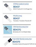
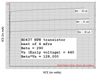
However the new (3rd) Edition of Art of Electronics has a handy table which suggests interesting candidates to study. One that leapt off the page was the medium power NPN device called BD437. As shown in Figure 1 below, numerous semiconductor companies offer the BD437 so I simply bought ten pieces from each manufacturer. The best of the best was pretty darn good, see Figure 2 below. Regrettably it's a relative low voltage (45V) device with relatively low fT (3 MHz), which places limits on its application.
_
Attachments
So far in my testing of PNPs the Sanyo 2SA1407E has been above average but not world-dominating on that Figure Of Merit.
However the new (3rd) Edition of Art of Electronics has a handy table which suggests interesting candidates to study. One that leapt off the page was the medium power NPN device called BD437. As shown in Figure 1 below, numerous semiconductor companies offer the BD437 so I simply bought ten pieces from each manufacturer. The best of the best was pretty darn good, see Figure 2 below. Regrettably it's a relative low voltage (45V) device with relatively low fT (3 MHz), which places limits on its application.
_
BD441 it's 80 V same family.
Calculating power MOSFET gate stopper value using datasheet params
Bob, take a look at US Patent 4,168,471 issued to Hitachi in 1979. On page 6 the inventor presents equations for the (complex) input impedance of the MOSFET operating as a source follower, in terms of datasheet parameters. In particular, equation 6 calculates the minimum necessary value of gate stopper resistance "R14" which ensures that the real part of the input impedance remains non-negative. The derivation is delightfully straightforward, as long as you take your time with the complex variables.
I imagine that a super-motivated graduate student, armed with these equations and a computer algebra package like Maple or Mathematica, could extend the analysis further and include (for example) the speaker cable too. Pretty neat!
Last edited:
Read the claims; the patented invention is two MOSFET source followers and two gate resistors connected in series, the purest example of which is Figure 5. The calculation of the series resistance is neither claimed nor patented.
However the issue date is Sept 1979 so this patent is now expired. But the analysis of negative-real-part input impedance still remains relevant today.
However the issue date is Sept 1979 so this patent is now expired. But the analysis of negative-real-part input impedance still remains relevant today.
Bob, take a look at US Patent 4,168,471 issued to Hitachi in 1979. On page 6 the inventor presents equations for the (complex) input impedance of the MOSFET operating as a source follower, in terms of datasheet parameters. In particular, equation 6 calculates the minimum necessary value of gate stopper resistance "R14" which ensures that the real part of the input impedance remains non-negative. The derivation is delightfully straightforward, as long as you take your time with the complex variables.
I imagine that a super-motivated graduate student, armed with these equations and a computer algebra package like Maple or Mathematica, could extend the analysis further and include (for example) the speaker cable too. Pretty neat!
Hi Mark,
Thanks, this is very relevant. I'll have to take a look at it. One question is whether they are just addressing the negative resistance issue under an output load, resistive or capacitive, as is usually an issue with a BJT emitter follower, or whether they are addressing a cause of the negative resistance that results from parasitic inductances.
Obviously, it is an area of interest because we don't like to kill the HF response of the MOSFET any more than necessary by use of an unnecessarily large gate stopper resistor.
Hafler used 470 ohms on the 2SK134 and 220 ohms on the 2SJ49 in the DH220.
Also, I recall using a gate Zobel network with the vertical MOSFETs in my MOSFET amplifier with error correction many years ago, so as to keep the impedance reasonably real while being able to use a smaller gate stopper resistance.
Finally, I think these issues can be quite dependent on the characteristics of the driver stage and VAS.
If the analysis just is based on load, and not on any parasitic inductances, the oscillation issue and its cure should show up on a SPICE simulation if the model of the MOSFET is not too terrible.
I'll take a look at the patent.
Cheers,
Bob
...the patented invention is...source followers...
It is almost assumed source followers will be used for an audio power amp and they have been analysed in detail, as in the patent.
Does anyone here know of any published analysis of Common Emitter outputs?
They are now more frequently used in op-amps for power efficiency and a similar improvement in audio amps would be nice.
The lower environmental impact wouldn't hurt either.
I asked this in a separate thread, with little response, surely someone has analysed this.
Bob?
Best wishes
David
Many people, including me, are wary of common emitter (or common source) output stages for power amps driving 4 ohm loads, because the open loop output impedance is so high. Nevertheless David Hafler did sell the TransNova power amp (description here) and some people really liked it. I believe some of Nelson Pass's class A Firstwatt amplifiers use common source output stages as well.
And I suppose you can say that an output stage using CFP / Sziklai connected devices, is a kind of common emitter amplifier with lots of local feedback applied -- but it only swings up to (Vrail - 2VBE), while a true common emitter output stage would swing to (Vrail - 0.5VBE) or so.
And I suppose you can say that an output stage using CFP / Sziklai connected devices, is a kind of common emitter amplifier with lots of local feedback applied -- but it only swings up to (Vrail - 2VBE), while a true common emitter output stage would swing to (Vrail - 0.5VBE) or so.
That's actually the topic for the article I am writing, albeit very slowly, for Linear Audio.
I'll look forward to it!!
Cheers,
Bob
Many people... are wary of common emitter ... because the open loop output impedance...
But the open loop does not matter, once the amplifier loop is closed the CE has the same output impedance as the EF.
After all, the Emitter Follower is just a CE with local feedback, that's why the output impedance is low.
So there should be no difference, at least to first order.
David Hafler did sell the TransNova power amp... I believe some of Nelson Pass's class A Firstwatt amplifiers use common source output
I was unaware of the Hafler, I have looked at the Pass a little but I haven't found any analysis.
Thanks for the Hafler information and reminder to ask in the Pass sub-forum.
CFP / Sziklai connected devices, is a kind of common emitter amplifier with lots of local feedback applied...
Theory concludes that local feedback would be better applied as overall feedback, another benefit that CE looks to have over an EF OPS.
Perhaps a more detailed analysis turns up subtleties that I have missed, that's what I am interested in.
Best wishes
David
A quick look at the Hafler link, it seems a bit umm... how to be polite, not detailed?
But a useful clue to follow up.
Last edited:
It is almost assumed source followers will be used for an audio power amp and they have been analysed in detail, as in the patent.
Does anyone here know of any published analysis of Common Emitter outputs?
They are now more frequently used in op-amps for power efficiency and a similar improvement in audio amps would be nice.
The lower environmental impact wouldn't hurt either.
I asked this in a separate thread, with little response, surely someone has analysed this.
Bob?
Best wishes
David
Common emitter output stages are often used in op amps to get rail-rail output swings. For power amps, the only common emitter outputs I am aware of are CFP output stages, of which I am not a fan. I indicated that in my book. Doug Self seems to like them, but he has to starve them of bias in order to get them to approximate meeting the Oliver criteria. They usually have a very small class A region. They are also not great at turning off the output transistors fast when needed. Sometimes they also have stability issues as well, since they include an explicit local negative feedback loop. This local feedback linearizes the individual top and bottom halves, but does not help the linearity of the signal splice that occurs at crossover.
The CFP does have the advantage of improved bias stability under some conditions, since the base-emitter drop of the output transistor is not a strong factor in setting the bias. However, if one wants to approximate the Oliver criteria, maintaining the optimum bias is more critical.
Just because a CFP includes a CE-connected output transistor does not mean it can swing all the way to the rail. Headroom for the driver must be considered.
Output stages with gain are usually CFP-based, where the local feedback factor is less than unity. Output stages with gain make life easier for the VAS, but distortion in the VAS is often not a problem.
The Bryston output stage is a variant of the CFP output stage that includes an opposite-sex "helper" output transistor. It can also be thought of as an emitter-follower output stage that includes a CE-connected "helper". It is a somewhat elegant arrangement that makes the signal current in the driver transistor do double duty.
Cheers,
Bob
The problem is confounded by many cases where the oscillation is actually related to the feedback loop of the amplifier, and wrongly attributed to parasitic oscillation of the output devices.
Perhaps the best way to separate the issues of local parastic oscillations from oscillations whose origin is related to the global feedback loop is to just change the compensation of the feedback loop to be much more conservative. An example of this would be to temporarily change the compensation to yield a smaller ULGF by a factor of 2.
Cheers,
Bob
once the amplifier loop is closed the CE has the same output impedance as the EF.
That's not what the textbooks say.
The textbooks say that CLOE = OLOE / (1 + (OLG * FBfactor))
CLOE = closed loop output impedance
OLOE = open loop output impedance
OLG = open loop gain
FBfactor = feedback factor (equals 1/21 in all power amps in Cordell's book)
The point here is that CLOE is OLOE times a constant. If amp#1's open loop output impedance is 1000X lower than amp#2's open loop output impedance, when you close the loops amp#1's output impedance will be 1000X lower than amp#2's. Feedback doesn't make them the same, feedback reduces each of them by the same multiplicative constant.
.... For power amps, the only common emitter outputs I am aware of are CFP...
I share your concerns about CFP, when used for class B+ anyway.
Dr Ed Cherry has done a CE OPS audio power amplifier, just on the way to the university library to check it out.
I assume that industry must have done some analysis of those rail-to-rail output op-amps, hoped that your insider experience would help here, thanks.
Best wishes
David
That's not what the textbooks say.
The textbooks say that CLOE = OLOE / (1 + (OLG * FBfactor))
Yes, but the point is the CE version now has increased OLG.
The gain that was used locally in the EF is now pushed into the OLG and it all cancels out.
Dr Ed Cherry has discussed the point in IEEE Circuits and Systems, Mar 2008. in a lot more detail, includes load effects that your simple Black model does not consider, but it's not an easy read.
He also has an article on precisely this point in JAES that is probably more easily comprehensible but I have only skimmed it, on my way to reread it.
Best wishes
David
- Home
- Amplifiers
- Solid State
- Bob Cordell's Power amplifier book