Hi All, Thanks for that input.
My no load THD analysis is now working just fine .
.
I read over section 3.11 in bob's book and added the required input and output networks. I left off the input coupling capacitor (which I hope was the right thing to do as I want to keep the circuit dc coupled for THD analysis as per my interpretations of bob book.
---------------
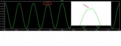
I did however notice some distortion in the collector of the differential amplifier and I was wondering if anyone could help me track down the source, as I check that it was not the changes that I just made to the circuit.
I check the DC operating points of the transistors and they don't seam to be entering saturation or cutoff. but I'm unsure how to check that over the entire AC input.
I have attached an image of the problem and my circuit schematic file.
My no load THD analysis is now working just fine
.I read over section 3.11 in bob's book and added the required input and output networks. I left off the input coupling capacitor (which I hope was the right thing to do as I want to keep the circuit dc coupled for THD analysis as per my interpretations of bob book.
---------------
I did however notice some distortion in the collector of the differential amplifier and I was wondering if anyone could help me track down the source, as I check that it was not the changes that I just made to the circuit.
I check the DC operating points of the transistors and they don't seam to be entering saturation or cutoff. but I'm unsure how to check that over the entire AC input.
I have attached an image of the problem and my circuit schematic file.
Attachments
Hi All, Thanks for that input.
My no load THD analysis is now working just fine
I read over section 3.11 in bob's book and added the required input and output networks. I left off the input coupling capacitor (which I hope was the right thing to do as I want to keep the circuit dc coupled for THD analysis as per my interpretations of bob book.
---------------
I did however notice some distortion in the collector of the differential amplifier and I was wondering if anyone could help me track down the source, as I check that it was not the changes that I just made to the circuit.
I check the DC operating points of the transistors and they don't seam to be entering saturation or cutoff. but I'm unsure how to check that over the entire AC input.
I have attached an image of the problem and my circuit schematic file.
Hi Stuart,
I always run my THD sims fully dc coupled, with no large capacitors in the circuit. I apply whatever dc offset to the input that is needed to bring the output offset to less than a couple of mV. Long time constants in a THD sim can mess things up.
The distortion you are seeing is effectively the error signal needed to drive the output of the amplifier to a nearly distortionless output. If the output stage is creating distortion, the error signal must have distortion. You may also see such a waveform if you look at the signal across the IPS differential inputs. Read the section in my book that discusses the concept of input-referred distortion.
Cheers,
Bob
The distortion you are seeing is effectively the error signal needed to drive the output of the amplifier to a nearly distortionless output. If the output stage is creating distortion, the error signal must have distortion. You may also see such a waveform if you look at the signal across the IPS differential inputs. Read the section in my book that discusses the concept of input-referred distortion.
Thanks Bob, I appreciate the feedback. I read section 22.10 Input-Referred Distortion Analysis in your book and found it very interesting.
I checked the emitter current of the driver & output NPN and PNP transistors. The emitter current waveform that they created was not the same so I am assuming that this is caused from the beta variations between the NPN and PNP transistors.
I went on and added the cascoded VAS (fig.3.12) and the double output stage (fig 3.13) and tested the distortion in the collector of the differential amplifier again. The distortion was gone.
Not really sure why this has happened but from reading section 22.10 I can only assume that possibly this distortion had disappeared or became very minimal due to the increase in forward path gain, which was a result of adding the cascoded VAS the the circuit.
Is this a correct assumption?
Also I was wondering is the anyway that you can compensate for the gain difference between NPN and PNP transistors?
Hi Stuart,
Not sure about the answer to the question about why the distortion became much smaller, but greater forward gain after the pint you are looking at is usually the reason.
I don't usually try to compensate for beta variations between p and n devices because beta is usually all over the place anyway. Some folks match p and n beta on a device-by-device basis. The main thing to keep in mind is that a good design does not have its performance depend much on transistor beta as long as the beta is reasonably high and the design itself has enough current gain in key stages. Examples are the 2EF VAS and the output Triple.
Cheers,
Bob
I think this is indeed logical.
The disappearance (or decrease) of the distortion in the input stage collector would point to a better open loop linearity of the amplifier.
Since the input diff stage works on the difference between input and (a sample of) the output signal, this is where you find the distortion, which then appears in the collector as a sort of 'pre-distortion' to get a distortion-less output signal.
If the amp is very linear in open loop, there is less 'pre-distortion' required to get a distortion-free output.
Jan
For those who don't know yet, Analog Devices is buying Linear Technology. That powerhouse may compete well with TI, who sucked up Burr Brown and National in recent years.
Cheers,
Bob
Let's hope that happens!
We need more vendors competing for our interest and money. The marketplace today is too much of a monopoly.
For those who don't know yet, Analog Devices is buying Linear Technology. That powerhouse may compete well with TI, who sucked up Burr Brown and National in recent years.
Cheers,
Bob
I hoping that that LT products don't start disappearing like the National stuff has with TI.
Particularly some of the op amps.
I hoping that that LT products don't start disappearing like the National stuff has with TI.
Particularly some of the op amps.
That's what I am worried about. I remain very angry with TI.
Consolidation does generally mean less competition.
Cheers,
Bob
Bob, when do you expect the next edition of your book? For some reason the current version is rather difficult to source in the UK with non-Kindle versions going for some 'extreme' prices. Any idea what the International Eastern Economy Edition is?
https://www.amazon.co.uk/gp/offer-listing/007164024X/ref=dp_olp_all_mbc?ie=UTF8&condition=all
I have the Kindle version but it will be the last time I purchase a technical book in that form. (I just purchased the paperback version of Self's text as I found the Kindle version of that frustrating as well.)
... and LTSpice?
See the discussion not the LTspice Yahoo group. People more worried about the 'key man' risk of Mike E leaving. But maybe it means better Analog Devices models become available in "ADspice".
... and LTSpice?
I can assure you that there will be no abandonment of LTspice.
Cheers,
Bob
Bob, when do you expect the next edition of your book? For some reason the current version is rather difficult to source in the UK with non-Kindle versions going for some 'extreme' prices. Any idea what the International Eastern Economy Edition is?
https://www.amazon.co.uk/gp/offer-listing/007164024X/ref=dp_olp_all_mbc?ie=UTF8&condition=all
I have the Kindle version but it will be the last time I purchase a technical book in that form. (I just purchased the paperback version of Self's text as I found the Kindle version of that frustrating as well.)
I'm working very hard to get it published and available within the next six months. I am quite a bit behind my original goal, and this sort of thing always takes longer than expected. Plus, I am an optimist.
I am not a fan of Kindle for technical books. Only about 10% of my sales are Kindle. 100% of the piracy is from the Kindle version. The DRM for Kindle has been cracked and there is software that will convert a Kindle file to PDF. If it was up to me, I would not have the publisher make a Kindle version available.
I don't know why, but the price paid for it on Amazon has gone up and down quite a bit in the last 6 months.
Cheers,
Bob
For those who don't know yet, Analog Devices is buying Linear Technology. That powerhouse may compete well with TI, who sucked up Burr Brown and National in recent years.
Cheers,
Bob
Bob, there's a tread about it here: http://www.diyaudio.com/forums/lounge/294740-analog-devices-buy-linear-tech.html#post4784929
Jan
That's what I am worried about. I remain very angry with TI.
Consolidation does generally mean less competition.
Cheers,
Bob
It could be the end of my oscillator.
I hoping that that LT products don't start disappearing like the National stuff has with TI.
Particularly some of the op amps.
Yet it stands to reason that that is exactly what will happen. LT's strengths is in their power products, ADI is (sort of) king in opamps.
So they will continue LTs power products but it makes sense (for ADI) to absorb the opamp and related overlapping stuff within ADI's portfolio.
Jan
I can assure you that there will be no abandonment of LTspice.
Cheers,
Bob
... thats really good to hear!
BTW: just downloaded and tested LTSpice XVII / 64bit variant!
Installable and running under Linux using the wine emulation environment.
Simulation results of my newest lateral mosfet amplifier are very similar to LTspice IV results.
BR, Toni
- Home
- Amplifiers
- Solid State
- Bob Cordell's Power amplifier book