At the first moment i have imagined the tripple darlington was the issue..then i have removed the first from the three stages, re adjusted the floating emitter resistor to 220 with the output back to EF double darlington..
I cannot reduce this capacitor below 130pF without face oscilations...with three stages at the output, with two stages and tried even with a single stage... please, confirm this value.... and....if you wish, tell a little bit more about this circuit.... i know it was made to "see" higher impedance.
I have readed your excellent book, but sadly the circuit i chose to try if driving me crazy.
I have used a very modified circuit into the Mark One...but even this way the circuit is unable to work with 33pf..... less than 130pf it starts to oscilate.... wave form becomes an amplitude modulated carrier with some few Megahertz in the carrier.
Circuit really reduces distortion but square wave form resulted very bad....not a good slew rate...raise time no good.
Is this 30pf just a reference?
Thank you,
regards,
Carlos
Hi Carlos,
I'm sorry to hear you are having trouble.
Can you tell me which Figure number in the book you are referring to?
Cheers,
Bob
MOSFET source resistor
Hi Bob,
I am building a MOSFET amp with IRFP240/9240. I your book page 233, "Use of Source Resistors" you suggest to use dissimilar Source resistor to reduce crossover distortion, 0.15R for N-channel and 0.22R for P-channel mosfet.
Could you explain why you choose higher Source resistor for the P-channel mosfet, I would expect otherwise, lower Source resistor for the P-channel mosfet as it has lower Transcounductance. For example, Wishay IRFP240 min Transonductane is 6.9 S and for IRFP9240 it is 4.2 S.
One other thing I notice that your Spice models for those MOSFET have the Transconductance in reverse, IRFP240 Kp=4.8 and IRFP9240 Kp=9. Why so?
Best regards and Happy New Year
Damir
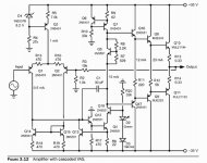
Page 68 dear Bob..... figure is attached... 3.12 is the fig. number
Question is simple...considering that i will be using the same output, is C1 value correct?
I need a simple answer...yes or no..then i will search for my own mistakes in the pcboard parasitic capacitances and inductances.
My circuit is modified..but current to VAS is the same and output i built the same to check this capacitance value.... i will modify my way...but i need to know if this value is correct or if was a revision mistake...maybe 130pf is the value, as i found it as the smallest stable value to use in my particular circuit.
Values in the VAS are different..but i made it the same as your schematic to check because my way was not working...but your way also not worked....i have built the VAS, and the output the same as your schematic in order to check the value..also the VAS current is the same you use..also the supply voltage is the same you use....made this way to check....then i will make it my way as the input is different in my circuit and also the output.
Thank you in advance by the time spent.
regards,
Carlos
Attachments
Last edited:
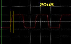
Raise time, in the Simulator and also in my scope resulted not that good
See.... 20 Khz raise time..... 1/3 power
So, i imagine some mistake i have made or revision error in your book...but i believe more in my own mistake as you are a great designer.
My unit, my particular unit...this one i have built.... is measuring even worse when watching the scope display....so....i do think something is wrong.
Sonic signature is nice.... very flat....no audible peaks in any particular frequency range.... well...my input and output, while listening, was very different than yours..also the values in the VAS different too.... returning to your schematic i found some peak in treble..despite the slew rate that sign to us that treble would be not that good....but was fine and the sonic signature felt into the treble at my home.
regards,
Carlos
Attachments
Last edited:
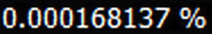
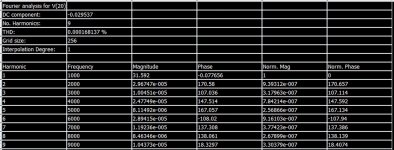
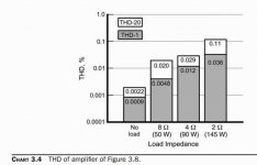
Your amplifier, dear Bob, can measure very low THD
Very good one.... have beated mine Dx Mark One.
Well....it can go lower if i figure out how to use 33pf as compensation
Your amplifier goes much lower than 0.0048% loaded with 8 ohms.... but have to tweak and get out from the exactly calculated values..some drift from the optimize values reduces THD.... some out of the box thinking.
Your Cascode VAS is a great contribution to our community.... great one.... i may use your circuit if i figure out (or if you help me) how to use 33pf as compensation.
regards,
Carlos
Attachments
Last edited:
Hi Mr. Cordell.
I have a question after seeing Carlos using your schematic in Fig. 3.12 in page 68 in your book.
I am hesitant in building a SS power amp for the reason that you described the complementary differential stage is superior because it's lower distortion. I always have a believe that for good sound, less is more. I really don't want to build the complementary differential input. Not only you have to double the LTP stage, you have to put in over current protection to avoid the VAS from drawing excess current. The more circuit, more more chance to cross couple and susceptible to EM interference.
Thanks and Happy New Year.
Alan
My question to you is: Is it true that the only disadvantage of the non complementary differential input stage is more even harmonics? Which is mainly 2nd harmonics? If that is the case, it's not the end of the world. From my understanding, it's the odd harmonics ( particular 3rd) that is offensive and unpleasant to the ears. Even harmonics are ok. particularly 2nd gives the warmth.
I think you may have misread Cordell
complementary diff input stages are largely eye candy - very little additional distortion cancellation occurs
possibly a little base current cancellation could happen, or not
since N vs P conductivity differs there are no exactly complementary Q pairs
push-pull, "complementary" VAS may have more going for it - but doesn't require input to be complementary diff pairs
Chapter 7.3, Page 136 stated what I said.I think you may have misread Cordell
complementary diff input stages are largely eye candy - very little additional distortion cancellation occurs
possibly a little base current cancellation could happen, or not
since N vs P conductivity differs there are no exactly complementary Q pairs
push-pull, "complementary" VAS may have more going for it - but doesn't require input to be complementary diff pairs
Seems like most of the problem of non push pull VAS can be overcome by having a higher current sink. This will bring up the slew rate. Yes, again non push pull VAS has more 2H. But again, 2H might not be the worst in the world.
That's my major concern and I am looking deeply into designing tube power amp instead because of this. I just believe that if the circuit looks too complicated, it is.
I think you may have misread Cordell
complementary diff input stages are largely eye candy - very little additional distortion cancellation occurs
possibly a little base current cancellation could happen, or not
since N vs P conductivity differs there are no exactly complementary Q pairs
push-pull, "complementary" VAS may have more going for it - but doesn't require input to be complementary diff pairs
I agree, the case for obsessive complementarity is overstated all too often.
For older designs or designs with very low slew rate, an LTP will cancel even harmonics but leave behind 3rd harmonics which rise with frequency.
LTPs readily give low offset, low temperature drift, and inherent signal limiting because they turn off when overdriven, rather than further on.
It also has the advantage that when used with a current mirror, it tends to give the highest loop gain per cost/effort of any competing stage, without becoming very slow.
If you remove the current mirror from the LTP, it will not be much better if at all than other IPS options in terms of distortion (except maybe on slow amps), although it will be more difficult to keep offset low.
Increasing the current of the CCS in the VAS stage will speed up the slew rate. You just need enough current to charge and discharge the capacitance. No magic about this.So what is the benefit of a complimentary input stage apart from the input bias current cancellation. Is it the symmetry of the transient pulse obtained ?
Regards
Arthur
As shown in Fig. 7.1 in p128. if you increase I2 from 10mA to say 25mA, you'll increase the slew rate so that becomes a non issue. I can't find the book reference, but basically using ( I X t= V X C) where t is the time used for slew rate. So I=VC/t. if you know the C, you can plug in how many volts per uS into V and t. Then you can calculate the current I to give you the slew rate.
It doesn't matter if one side is faster as long as the slow side exceeds the minimum requirement of the slew rate.
Last edited:
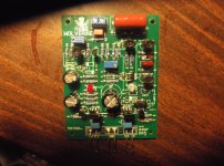
What's wrong with "obsessive complimentary". 
They don't have to be complicated (below).
"What are the benefits" ?? OMG
10ppm - soft clipping - saturation is "tamed" - 150+v/us slew (even with a VFA).
- get this slew rate with 5ma VAS currents
I was a "LIN" fan up until a year ago - those days are gone.
Thermally, some of the complimentary's will cancel to the uA (VAS I).
PS- LIN is still good for "industrial" duty (subs /PA)
OS
Attachments
Why worry about symmetrical clipping. You run into clipping, you need a bigger amp!!! Unless you are talking about PA system, how often you use 10W for home? If you have a 70W Class A amp.......hell even 30W Class A amp, you'll never use the full potential for home system. For PA, I doubt you care about the distortion that much.
Say for common +/-40V rail, say you give 10V head room. So you swing 30Vpeak. That is about 20Vrms. W=V2/R. you have 202/4ohm=100W for 4 ohm speaker with 10V head room.
Say for common +/-40V rail, say you give 10V head room. So you swing 30Vpeak. That is about 20Vrms. W=V2/R. you have 202/4ohm=100W for 4 ohm speaker with 10V head room.
Last edited:
Why worry about symmetrical clipping. You run into clipping, you need a bigger amp!!! Unless you are talking about PA system, how often you use 10W for home? If you have a 70W Class A amp.......hell even 30W Class A amp, you'll never use the full potential for home system.
For PA, I doubt you care about the distortion that much.
I have a "bigger amp" - I clipped the above at over 400W.
Any HT system at a believable volume will occasionally hit the max with a
digital source.
Still have my tweeters , too.
...as do the other builders. Users will clip their amps - unavoidable after a few glasses of wine and the monkey
curiosity to see what 500W peaks sound like.
EDIT - it is not just the overload behavior , but the "stress" that is put on
the preceding stages (saturation). A circuit like above will survive many
years of abuse AND sound as good as (others).
OS
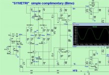
Bob's excellent example - better than Self ...
I wholeheartedly wish Carlos luck to use Bob's LIN example.
It works (below) ... I use it as my "tester" , as it is SO "rock solid"
at ANY rail voltage.
Spilled the wine on it - it still worked
PS - still , myself and most others prefer the "faster" complimentary
IPS's - they are more "engaging" (I no longer believe all amps sound the same).
OS
Attachments
When you clip, it's not going to sound good whether it's symmetrical or asymmetrical. Sounds like what you need is a lot of head room, a lot of swing in your case. Whether you use complementary or single end VAS with CCS tail is irrelevant. You can get a lot of swing with single ended VAS with CCS that pull heavier current. There is also an argument if you use complementary VAS, there are occasions that one side is going to turn off and you have crossover distortion also. with the CCS current tail, you don't turn off anything so you don't have crossover distortion.I have a "bigger amp" - I clipped the above at over 400W.
Any HT system at a believable volume will occasionally hit the max with a
digital source.
Still have my tweeters , too.
clip their amps - unavoidable after a few glasses of wine and the monkey
curiosity to see what 500W peaks sound like.
EDIT - it is not just the overload behavior , but the "stress" that is put on
the preceding stages (saturation). A circuit like above will survive many
years of abuse AND sound as good as (others).
OS
I think I am good with 30W to 50W amp. I don't listen very loud. I know how loud 20W can be. I have a few guitar amps, it is very hard to crank it up pass 10W. I have power scaling on my amps, I cannot take 10W at full blast.
What is LIN?
Last edited:
- Home
- Amplifiers
- Solid State
- Bob Cordell's Power amplifier book