Kgrlee if Peter Baxandall had used tubes (values) to make his point than really Jurassic devices would have applied . However the use of transistors move at least in to the tertiary devices. Old men have a different view of time than the less experienced folk. There is still time but do pass the beer.
Kgrlee if Peter Baxandall had used tubes (values) to make his point than really Jurassic devices would have applied . However the use of transistors move at least in to the tertiary devices. Old men have a different view of time than the less experienced folk. There is still time but do pass the beer.
All of us perceive time on somewhat of a log scale. When we were kids, a year was forever. As we grow older, the years pass much more quickly.
Cheers,
Bob
The VAS is indeed the PA stage that will show all-pass characteristics first. Michael, you may like to search for 'minimum phase of BJTs' on this website to remedy your ignorance of elementary analogue electronics.
There is no such thing as an "all pass" characteristic in respect of the TIS. Period.
There is no such thing as an "all pass" characteristic in respect of the TIS.
That's where it started. I've seen technobabble and cheerleading, but not a shred of coherent proof that an audio amplifier can be non minimum phase.
I've already mentioned before, the fact that the bipolar transistor current gain Beta exhibits a RHP zero at a frequency larger than the transition frequency Ft is a textbook fact (pp. 6).
However, this has no bearing with anything that resembles a TIS in an audio amplifier. The problem is not about abusing the "excess phase" concept, but the underlying attempt of selling the illusion that audio amplifiers have an extra degree of freedom in this respect. In fact, for any minimum phase system like an audio amplifier, once that the "maximum feedback" (in the Bode and/or Lurie sense) has been reached, it is impossible to further increase the loop gain without compromising the stability.
Period.
Last edited:
I've seen ... not a shred of coherent proof that an audio amplifier can be non minimum phase.
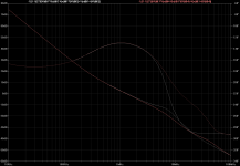
You may want to look at this one.
Clearly non-minimum phase, a surprise to me.
It is above the unity crossover frequency but sufficiently close to be of interest.
Pink trace is the result of an 820 pF capacitor in parallel with the VAS emitter resistor.
I have not yet worked out the details.
Circuit is from Toni's amp. http://www.diyaudio.com/forums/soli...b-power-amp-200w8r-400w4r-46.html#post3527899
Best wishes
David
Attachments
Last edited:
I now start to understand the old quote " youth is wasted on the young"All of us perceive time on somewhat of a log scale. When we were kids, a year was forever. As we grow older, the years pass much more quickly.
Cheers,
Bob
There is no such thing as an "all pass" characteristic in respect of the TIS. Period.
Mike,
I should have used the term non-minimum phase and or with a right-half plane zero. The term all-pass generally implies a flat frequency response, which the VAS obviously does not have. The Miller-compensated VAS most certainly does have an RHP zero, albeit at a high frequency.
If you feed a Miller-compensated VAS with an AC current source, and you assume that the transistor has high beta and high ft, then almost all of the input current flows through Cdom. At most frequencies, the VAS then acts as an inverting integrator, with the collector current of the VAS transistor essentially equaling that through Cdom. To make this collector current flow, a small amount of voltage from the input current must appear at the base, and that voltage is inversely proportional to gm of the VAS.
At very high frequencies Cdom begins to look like such a small impedance that the voltage at the base combined with gm does not produce enough collector current to equal that of the current through Cdm. In essence, at high frequencies where Cdom is like a short, the transistor just ends up looking like a resistor whose value is 1/gm. In this case, the applied input current merely appears across this resistance non-inverted. The functionality of the Miller integrator has thus transitioned from inverting to non-inverting, and is a non-minimum phase device.
Miller-compensated VASs that are degenerated have lower transconductance, so the frequency at which the impedance of Cdom equals that of 1/gm is lower. With Cdom = 100pF and 1/gm = 25 ohms, that frequency is approximately 60MHz.
Cheers,
Bob
For people with not enough background I can give hereunder some references explaining better my post; if they do not understand technically they can improve at least their technobabble skills
But first some terminology. An OTA is exactly what Davada has explained. A differential amplifier current mirror loaded is a simple OTA, an amplifier with high impedance input, high impedance output is analyzed as an OTA because high impedance input is a voltage input sensor and high impedance output is a current source so voltage in and current out so transconductance. The first two stage of an opamp is an OTA, a single stage folded cascode is an OTA. They are building blocks in IC design. If the second gm block is Miller compensated it is called a Miller OTA
When we analyze stability of feedback system it is custom to call singularities of the transfer function as right half or left half plane located. Root locus is drawn in this plane for a variable parameter usually the DC gain. The plane is the imag, real plan of complex values; drawing impedance or transfer function values for a variable parameter in this plane is called a polar plot in the polar diagram. Roots are called positive or negative in the polar diagram. This is pure terminology.. Stability is now analyzed by considering the positive or negative value of the input impedance or admitance
Lundberg (his paper: Internal and external opamp compensation) shows a very nice derivation of a Miller two stage OTA transfer function showing the second order denominator and positive zero numerator. The classical Gray and Mayer are deriving the same equations for a common emitter or a differential amplifier.
Roberge ( Operational amplifier : theory and practice ) shows the same and why this positive zero presents a difficulty in the drawing of the root locus and how to solve it. Roberge book is also excellent
If you use the drawing and equation of Lundberg for example you will see that the positive zero frequency is fz= gm2/2piC where C is the Miller capacitance and gm2 the second stage transconductance.
The dominant pole frequency is f1 =1/KC where K is a constant and the non dominant is f2= gm2/2piCl Where Cl is the loading capacitor This approximation holds for large values of C miller. If you plot the position of the pole/zero with respect to frequency for C as a variable, you see immediately by examination of the given expressions that fz decreases in frequency if C increases while f2 stays constant. At a certain value of C, the zero will be at a lower frequency than the p2 non dominant pole;
If you plot now the bode diagram of this transfer function you see first an horizontal from DC then a decrease after the first pole and then again an horizontal after the zero. The phase will go from zero to -90° after the first pole but then instead of going back to zero as with a negative zero, it continues towards -180° because of the sign in the numerator ( s-fz)
In the region beyond the zero and before the second pole, the amplitude of the transfer function is flat while the phase is gradually going to -180°. This is the charactérisric of an all pass ( in this zone). I am not saying that the stage is an all pass everywhere.
That's where it started. I've seen technobabble and cheerleading, but not a shred of coherent proof that an audio amplifier can be non minimum phase.
I've already mentioned before, the fact that the bipolar transistor current gain Beta exhibits a RHP zero at a frequency larger than the transition frequency Ft is a textbook fact (pp. 6).
However, this has no bearing with anything that resembles a TIS in an audio amplifier. The problem is not about abusing the "excess phase" concept, but the underlying attempt of selling the illusion that audio amplifiers have an extra degree of freedom in this respect. In fact, for any minimum phase system like an audio amplifier, once that the "maximum feedback" (in the Bode and/or Lurie sense) has been reached, it is impossible to further increase the loop gain without compromising the stability.
Waly,
Nobody has said that the closed-loop response of an audio amplifier is non-minimum phase (at least at frequencies not significantly greater than ULGF). Nobody has said that a non-minimum phase characteristic is a good thing for an amplifier or a useful extra degree of freedom.
What was referred to is the open-loop gain. Specifically, I noted that the Miller integrator can be a non-minimum phase circuit.
Rather than making absolutist statements about what you perceive to have read, you would do better to ask for clarification of what has been said, since there is often a better way that could have been said. Oftentimes, what people say for reasonable brevity may have unsaid caveats. It is perfectly reasonable to bring these caveats to people's attention or give the poster an opportunity to clarify by citing those caveats. This is how reasonable technical discussions are carried out, and everybody learns, rather than being confused by a person picking an argument.
Cheers,
Bob
<snip>I am not saying that the stage is an all pass everywhere.
Now it makes sense, and it is based on the classic interpretation of a RHP zero at the frequency that nulls the (inverting) output load current by the (non-inverting) current flowing through the Miller cap (that can be simply Cob).
However, I fail to see the relevance for audio amplifier applications. Audio amplifiers are minimum phase, period.
However, I fail to see the relevance for audio amplifier applications. Audio amplifiers are minimum phase, period.
So what about this one?
http://www.diyaudio.com/forums/soli...lls-power-amplifier-book-369.html#post3546769
Best wishes
David
What was referred to is the open-loop gain. Specifically, I noted that the Miller integrator can be a non-minimum phase circuit.
Speaking about putting words in people's mouth, who said otherwise? Have you looked at the link I posted showing exactly this, in the frequency response of a common emitter gain stage? Doesn't even need to be a TIS, or to be externally Miller-ized, only the Cob will do. Otherwise said, a common emitter gain stage is always a non-minimum phase system. Tubes, fets, mosfets, bipolars are, in this respect, all of the same breed.
The only problem is that we are talking about (stable) audio amplifiers, where this non-minimum phase behavior is totally irrelevant. All poles and zeroes are in the LHP, there is no "excess phase" to be minimized, and the phase and gain are directly related, through an elementary Hilbert transform.
The rest of the people here understand what I said, and I see no need to further argue with you. You are just picking an argument in a failed attempt to impress others on this forum. The only thing they are impressed with is your arrogance. Grow up.
The rest of the people here understand what I said, and I see no need to further argue with you. You are just picking an argument in a failed attempt to impress others on this forum. The only thing they are impressed with is your arrogance. Grow up.
Thank you for the free advice. I will, and report back ASAP with the results.
I am though not expecting this to change the fact that audio amplifiers are minimum phase systems, and hence there is no "excess phase" to minimize.
In the region beyond the zero and before the second pole, the amplitude of the transfer function is flat while the phase is gradually going to -180°. This is the charactérisric of an all pass ( in this zone). I am not saying that the stage is an all pass everywhere.
First, in what context are you using the acronym "OTA"? I.e. what does "OTA" stand for?
Secondly I have read Lundberg, Gray and Mayer, Solomon and Roberge from cover to cover. Nowhere in those works is it suggested, particularly with a BJT TIS, that the second pole (or first non-dominant pole) precedes the RHP zero.
As I have indicated previously, the RHP zero resides well beyond unity gain for a BJT TIS and is at a higher frequency than the first two dominant poles.
Therefore, at no point do you have a flat frequency response before unity gain due to the RHP zero. Moreover, due to the presence of non-dominant poles after the onset of the RHP zero it is highly improbable that you'll have a flat all-pass frequency response even after the RHP zero takes effect.
Last edited:
I am though not expecting this to change the fact that audio amplifiers are minimum phase systems, and hence there is no "excess phase" to minimize.
Are you being deliberately obtuse? You do realise that this is just a semantic argument? That Bob used the term "excess phase" in not strictly-speaking the "correct" or "usual" way? Indeed, that is why I put it in quotes when I tried to help out several posts ago.
Do you agree that if you take amplifier "A", with certain Ft and Cob transistors in its output stage, and you miller compensate it so that it has a ULGF of, let's say 500 kHz, and a phase margin of 60 degrees, the reason that it has a phase margin of 60 degrees and not 90 degrees is that there are high-frequency poles present in the system?
Do you agree that if you replace the output transistors with faster devices with lower Cob, this will likely now result in a higher phase margin? So now you can increase the ULGF to a higher frequency to get back to a 60 degrees phase margin? So now you have amplifier "B" with higher ULGF and therefore higher loop gain in the audio band and therefore (probably) lower distortion?
Bob was using the term "excess phase" to refer to the phase shift at ULGF contributed by the high-frequency poles. If you can make this "excess phase" smaller, by using faster devices, you can move the ULGF to a higher frequency whilst maintaining the same phase margin. That is all.
Last edited:
Gentlemen, there is no need to get rude over semantic issues.
How about yus young uns discuss a more useful topic like Michael's favourite 'VAS vs TIS'. Then he can demonstrate his facility and detailed understanding of Lundberg, Gray and Mayer, Solomon and Roberge.
Us old fogeys can just pass the beer and watch in admiration.
How about yus young uns discuss a more useful topic like Michael's favourite 'VAS vs TIS'. Then he can demonstrate his facility and detailed understanding of Lundberg, Gray and Mayer, Solomon and Roberge.
Us old fogeys can just pass the beer and watch in admiration.
Do you agree that if you take amplifier "A", with certain Ft and Cob transistors in its output stage, and you miller compensate it so that it has a ULGF of, let's say 500 kHz, and a phase margin of 60 degrees, the reason that it has a phase margin of 60 degrees and not 90 degrees is that there are high-frequency poles present in the system?
Do you agree that if you replace the output transistors with faster devices with lower Cob, this will likely now result in a higher phase margin? So now you can increase the ULGF to a higher frequency to get back to a 60 degrees phase margin? So now you have amplifier "B" with higher ULGF and therefore higher loop gain in the audio band and therefore (probably) lower distortion?
Bob was using the term "excess phase" to refer to the phase shift at ULGF contributed by the high-frequency poles. If you can make this "excess phase" smaller, by using faster devices, you can move the ULGF to a higher frequency whilst maintaining the same phase margin. That is all.
Absolutely agreed on all counts.
Now, please explain where is the "all pass", non-minimum phase properties come into play. High frequency poles and/or the extra phase shift created by a slow output stage have nothing to do with this.
There is absolutely no reason for distorting and/or abusing well understood and established concepts. If I would attempt such a change in the meaning of "excess phase", I would probably fail the control theory exam.
But then, quod licet Jovi, non licet bovi.
- Home
- Amplifiers
- Solid State
- Bob Cordell's Power amplifier book