I agree with Mr Cordell here, that doesnt look good at all, peaking looks in the region of 2db, my guess that circuit is either on the verge of oscillation or already oscillating. That plot looks like one taken from after the inductor, what does it look like before ?
That circuit does not oscillate, and the plot was taken before the inductor. I could not provoke it to oscilate with .tran function.
Next plot(#3176) was simulated with the drivers compensation not predrivers as I wrote it(it is EF2 OPS) and that plot does not have any peaking but the slope does not fall monotony.
BR Damir
If you are just simulating his circuit, why not use Bob's devices and leave in the bits which affect stability, good or bad.
You can then compare the sims with his 'real life' results.
If you are recommending 'improvements', why not show your sim performance results to compare with his sims and also his 'real life' results.
If a sim shows a particular device change or 'improvement' results in worse performance/stability than a sim of something with known good 'real life' performance/stability, perhaps its a gentle hint from above not to move in that direction.
Why not start with something which works well in 'real life' and seems to tally with the sims?
______________
Can you post your plots which show 'minor loop is unstable'? Is that with the .ASC you posted in #3170?
I have already posted plots demonstrating the instability of the minor loop in Bob's three transistor TIS here:
http://www.diyaudio.com/forums/soli...lls-power-amplifier-book-313.html#post3502347
I hope these are clear enough for you.

That circuit does not oscillate, and the plot was taken before the inductor. I could not provoke it to oscilate with .tran function.
Next plot(#3176) was simulated with the drivers compensation not predrivers as I wrote it(it is EF2 OPS) and that plot does not have any peaking but the slope does not fall monotony.
BR Damir
Hi dodod,
The cloesed loop gain in that plot does fall monotonically. It just has a change in the slope, which is OK.
Cheers,
Bob
I have already posted plots demonstrating the instability of the minor loop in Bob's three transistor TIS here:
http://www.diyaudio.com/forums/soli...lls-power-amplifier-book-313.html#post3502347
I hope these are clear enough for you.
Hi Mike,
Try it with the emitter resistor I use and see what you get. Also, ditch the emitter-to-emitter caps used on the pre-driver and drivers. They are irrelevant and we want to make sure they are not causing any funny business.
There are 2 issues of interest here:
1. Whether your circuit adequately represents my circuit.
2. Given that you have a circuit that exhibits instability, why does that instability not show symptoms of peaking at the VAS output under normal operating conditions.
Cheers,
Bob
As I have already noted, I have simulated the circuit with the emitter resistor and found that although it reduces minor loop transmission, it does not improve stability margins, and, indeed, worsens them in this case.
The cross-coupled capacitors in the drivers are not irrelevant; they help expedite the extraction of charge from the output stage as Andy_C demonstrated many years ago. Admittedly, they shouldn't be larger than 1uF, but, in any case, they do not affect minor loop transmission in any way.
Your three transistor TIS remains unstable even when a unity gain ideal VCVS is used for the output stage.
Hi dodod,
The cloesed loop gain in that plot does fall monotonically. It just has a change in the slope, which is OK.
Cheers,
Bob
Thanks Bob for your comment. I was thinking that monotonically means with the same slope all the way down.
BR Damir
Not true.
Actually it must be true.

Im more inclined to believe manufacturers who have been in business for over 30 years and have extensive experience than Id have in believing your view especially when my own experience is in line with the said manufacturers views.
I quote from a national semiconductors datasheet :
"A network analyzer can be used to determine the inherent stability of a system. An output vs frequency curve generated by a network analyzer can be a good indicator of stability. At high frequencies, the curve shows whether a system is oscillating, close to oscillation, or stable. Several different phenomena can occur. In one scenario, the system is stable because the high frequency rolloff is smooth and has no peaking. One can decrease the frequency at which this rolloff occurs. Another scenario has some peaking at high frequency. If the peaking is 2 dB, the amplifier is stable as there is still 45 degrees of phase margin. As the peaking increases, the phase margin shrinks, the amplifier and the system, move closer to instability. The same system that has a 2-dB peak has an increased peak when a capacitane is added to the output. This indicates the system is either on the verge of oscillation or is oscillating, and corrective action is required."
Go and tell the engineers at National they are wrong.
Actually, I was referring to the difficulty in establishing, from the closed loop frequency response from which the major loop may be stable, whether internal loops are stable or not. This is not necesarily possible in my experiance.
You have to separately establish the stability of internal loops, such as the Miller feedback loop, by independently measuring their loop gain with frequency. This is elementary.
You have to separately establish the stability of internal loops, such as the Miller feedback loop, by independently measuring their loop gain with frequency. This is elementary.
Last edited:
That circuit does not oscillate, and the plot was taken before the inductor. I could not provoke it to oscilate with .tran function.
Next plot(#3176) was simulated with the drivers compensation not predrivers as I wrote it(it is EF2 OPS) and that plot does not have any peaking but the slope does not fall monotony.
BR Damir
One can many times have a amp stable with such a plot but it could maybe be made unstable with certain loads. Note that the plot from post 3176 is much more desirable in my view as this doesnt really have any peaking, maybe 0.3 db ?
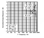
See the following plots as examples:
In the first when rf = 1k there isnt any stability problem (peaking below 2db), when rf=820 there is some concern, at rf=620 its either on the verge of oscillating or already unstable.
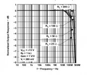
In the next plot there is only some concern when rl=200.
Attachments
Manso,
the 1k plot in the left diagram shows peaking.
The peak is well below the 0 ref level.
But if you were instead to compare the peak to the plot that by 130MHz would be way below -2dB. The peak height is indeterminate (for me) since I cannot estimate where the attenuation would be if the peak were removed.
In the right hand graph the Rl=100r is showing considerable peaking.
Rl=25r is also showing an anomaly, whereas Rl=50r seems like a very gradually increasing roll off steepness.
Actually, I was referring to the difficulty in establishing, from the closed loop frequency response from which the major loop may be stable, whether internal loops are stable or not. This is not necesarily possible in my experiance.
You have to separately establish the stability of internal loops, such as the Miller feedback loop, by independently measuring their loop gain with frequency. This is elementary.
This is exactly what kgrlee was asserting as I understood it, that any anomolises in the minor loops would show themselves in the closed loop response such as peaking. National are basically making the same statement. It takes a lot of practical experience to come to this conclusion but Ive had the same experience in limited experience, as long as the closed loop response falls monotonically like Bob Cordell says, there is absence of any substancial peaking ( around 2 db or more) the systen is going to be stable. This in reverse would suggest everything is fine in the minor loops.
Maybe someone can show a plot and a built circuit showing the oscillation where this is not the case ?? The amp mentioned in Bobs book is unfortuneatly not built so cant be used.
Referencing the response peak above, at what point is this peak in response not a concern? Is there a point where it is so far away from unity that it does not matter? Or is it always a concern?
If I understand correctly I would say when these peaks are at frequencies higher than ULGF and gain margin is good (10db min). This is my experience though, someone else with different viewpoint or experience ??
If I understand correctly I would say when these peaks are at frequencies higher than ULGF and gain margin is good (10db min). This is my experience though, someone else with different viewpoint or experience ??
Sorry my question wasn't phrased that well but yes your understanding was correct.
My thoughts were that you reach a point where the max frequencies of your medium and power devices are reached and this would have an effect on the closed loop gain plot. Would this mean that using the closed loop gain plot to look for local instabilities is no longer valid when looking at these frequencies? The effect of the maxing out of power devices may causing peaking themselves but not the sort of peaking that would suggest local instability problems.
...any anomolises in the minor loops would show themselves in the closed loop response such as peaking.
This is precisely what I dispute: minor loop instability may not show itself in the amplifier's closed loop frequency response. I know this for a fact.
Last edited:
As I have already noted, I have simulated the circuit with the emitter resistor and found that although it reduces minor loop transmission, it does not improve stability margins, and, indeed, worsens them in this case.
The cross-coupled capacitors in the drivers are not irrelevant; they help expedite the extraction of charge from the output stage as Andy_C demonstrated many years ago. Admittedly, they shouldn't be larger than 1uF, but, in any case, they do not affect minor loop transmission in any way.
Your three transistor TIS remains unstable even when a unity gain ideal VCVS is used for the output stage.
Hi Mike,
Sorry, I must have missed your stating that you had simulated the circuit with the emitter resistor in place.
I am well aware of the reason for those capacitors; I was suggesting to leave them out to minimize any possible variables. I was just thinking that if you want to refer to it as "my" circuit you should make it basically the same.
Thank you for simulating it with an ideal unity gain output stage; that takes out those variables.
Can you confirm that you simulated the circuit with the VAS all together, everything in closed loop, and saw no peaking at the VAS output?
If you did this and did not see peaking at the output of the VAS, then this remains quite curious.
My simulation of my circuit shows no evidence of peaking in closed loop response either at the output or at the VAS, out to beyond 100MHz.
My evaluation of the VAS loop shows a phase margin of 35 degrees at a ULGF of around 40MHz.
This is still a head-scratcher.
Cheers,
Bob
Can you confirm that you simulated the circuit with the VAS all together, everything in closed loop, and saw no peaking at the VAS output?
If you did this and did not see peaking at the output of the VAS, then this remains quite curious.
Sorry, Bob; it would appear you are right after all; my mistake was to simulate the closed loop frequency response with an insufficient bandwidth.
I can report that there is some peaking in the closed loop frequency response well beyond the audio band, apparently corresponding to an unstable minor loop, which virtually disappears when you use a 220pF shunt capacitor at the output of the three transistor TIS.
My simulation of my circuit shows no evidence of peaking in closed loop response either at the output or at the VAS, out to beyond 100MHz.
My evaluation of the VAS loop shows a phase margin of 35 degrees at a ULGF of around 40MHz.
Perhaps your transistor models are at fault?

A french chap in the link below describes his trials and tribulations when he tried the cascoded beta enhanced TIS; I am not sure about his "memory distortion" though:
Memory Distortion Philosophies - Part 8 : More tests
More on "memory distortion":
http://www.lavardin.com/lavardin-techE.html
Last edited:
Sorry, Bob; it would appear you are right after all; my mistake was to simulate the closed loop frequency response with an insufficient bandwidth.
I can report that there is some peaking in the closed loop frequency response well beyond the audio band, apparently corresponding to an unstable minor loop, which virtually disappears when you use a 220pF shunt capacitor at the output of the three transistor TIS.
Perhaps your transistor models are at fault?
A french chap in the link below describes his trials and tribulations when he tried the cascoded beta enhanced TIS; I am not sure about his "memory distortion" though:
Memory Distortion Philosophies - Part 8 : More tests
More on "memory distortion":
Lavardin Technologies High End Audio Systems - Technologies
Hi Mike,
At what frequency was the peaking, and how much peaking was there.
I assume this was at the output of the amplifier. Dis you look at peaking at the collector of the VAS?
Please do me a favor and try my models.
Cheers,
Bob
Attachments
- Home
- Amplifiers
- Solid State
- Bob Cordell's Power amplifier book