In the 80's & early 90's I would have claimed most (all?) Hi-end Golden Pinnae amps behaved like this.I have often wondered if a lot of the audible differences in amplifiers are a result of burst parasitic oscillations on perhaps a part of a cycle. Most of us have seen this in the lab when we have a border-line stable amplifier.
Think of all of the well-intentioned hi-end designers who don't even use SPICE and may not be excruciatingly thorough about checking for traces of instability in their amplifiers under a myriad of loads. These high-end amplifiers could sound different from one another, especially if you throw in some boutique cables and maybe some nasty high-end speaker loads.
This was certainly the case with several on Stereophile & TAS A lists I measured & listened to in Jurassic times. No wonder they were fussy about speakers and sounded different from each other

Most of the time, this 'parasitic' instability is obvious on a cheap scope. Drive the amp at various levels & frequencies. A switched capacitance box is good and quick for pure capacitive loads.
Also worth trying is a big guitar speaker at frequencies just above resonance.
More subtle cases can't be seen on a cheap scope but lead to much higher than expected distortion on very specific loads & speakers.
Not sure I've seen the assertion before in the way it is meant here.
It is very important to understand that we are not talking about the usual peaking around ULGF brought about by phase margin, like your example of peaking due to phase margin of 45 degrees. This is quite well-understood.
Here we are talking about relative peaking at higher frequencies, above the ULGF, and more in the vicinity of the frequency where gain margin is evaluated (GMF). For an amplifier with a ULGF of 1MHz, the peaking we are talking about here might occur at, say, 5-10MHz or higher. This is not peaking with respect to the nominal closed loop gain of the amplifier. These peaks may not come up anywhere near that reference. I have casually described these peaks as the closed loop gain above ULGF as not falling monotonically.
In some cases, local loop instability in the amplifier may occur at rather high frequencies, perhaps in the 10's of MHz - see Mike's post a few pages back in regard to stability of the local Miller compensation loop around a Darlington cascode VAS, wherein the signal goes through three transistors in traversing that loop.
Cheers,
Bob
The assertion was that if the closed loop gain looks OK, then the internal loops are OK. I wasnt thinking of the frequencies above ULGF. Regarding the peaks above ULGF these in my experience havent been of any concern at all if they do show some peaking, as long as gain margin is a min 10 db which I usually shoot for.
The assertion was that if the closed loop gain looks OK, then the internal loops are OK. I wasnt thinking of the frequencies above ULGF. Regarding the peaks above ULGF these in my experience havent been of any concern at all if they do show some peaking, as long as gain margin is a min 10 db which I usually shoot for.
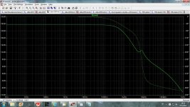
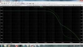
Does this Closed Loop Gain look OK, ULGF is 720kHz?
Damir
Attachments
The assertion was that if the closed loop gain looks OK, then the internal loops are OK.
Not true.

The assertion was that if the closed loop gain looks OK, then the internal loops are OK. I wasnt thinking of the frequencies above ULGF. Regarding the peaks above ULGF these in my experience havent been of any concern at all if they do show some peaking, as long as gain margin is a min 10 db which I usually shoot for.
As far as global loop stability goes, it is generally my experience that none of the relative peaking I describe above ULGF will occur if gain margin is at least 10dB. I agree that 10dB is a good goal.
However, if there is peaking in local loops, then there may be peaking in the closed loop response above ULGF even if global gain margin is OK. This kind of behavior should be a caution flag.
Finally, if there is local loop instability at a frequency will above the gain margin frequency at, say 30MHz, then this might not be evident in the closed loop response. It might not make it through the output stage, for example. This is the part of the assertion that internal loops are OK if closed loop response is OK that might not be valid.
You might be able see see evidence of it if you probe the emitter of the predriver in a Triple with a 10:1 probe on a wideband scope.
Cheers,
Bob
Does this Closed Loop Gain look OK, ULGF is 720kHz?
Damir
No, that peak is not OK in my opinion, and may be a red flag for local loop stability concerns. Something is going on there at 9MHz.
Cheers,
Bob
Not true.
Hi Mike,
This is the core of the question regarding how well the closed loop gain gives a warning of local loop instability. You may very well be right about that assertion not being true.
Can you expand on why you believe it to be untrue?
BTW, can you send me the asc file of the amplifier schematic simulation of my amplifier of figure 3.12 that you analyzed several poss ago? I was unable to read some of the values you used and want to be sure to evaluate the exact same thing.
Cheers,
Bob
Hi Bob,
I did some simulations in an ideal circuit, did confusion, I say that capacitor in LTP has high attenuation, this is not true at the output of LTP the attenuation is 6dB/8°, The global effect can result in a high attenuation.
Here is my circuit and simulations:
I found best with a LTP real, the second order filter at the exit leave the circuit unstable.
Hi Rafael,
The circuit you show does not represent the way I would simulate the VAS with Miller effect. You need to make it look like a transimpedance stage with Cm as the feedback element. For this reason, I would be reluctant to trust these results.
Cheers,
Bob
Bob, here is that .asc. Note that i use zetex models and KSC2690A/KSA1220A and Andy_C's MJL3281A/MJL1302A models which in my experiance are good models. I can send them to you by email. If you're interested send me mail.
Attachments
Last edited:
You can have a closed loop frequency response plot that gives no indication whatsoever in simulation that the minor loop is unstable as is the case with your figure 3.12.
Hi Mike,
If the minor loop is unstable or has very small phase margin, will it not show a peak in its own gain at its frequency of instability? For example, the VAS in the example, with a Miller capacitor around it, and with peaking around 30MHz, would seem to exhibit a peak in its transimpedance response when it is being driven in normal operation in the amplifier when the amplifier is being driven closed loop and swept through 30MHz.
Indeed, in the SPICE simulation, if you probe the output of the VAS, I would expect you would see a peak there if the VAS is only marginally stable. Bear in mind that what I am talking about at this point is really the closed loop response of the VAS.
Cheers,
Bob
I have simulated your fig. 3.13 where the minor loop is unstable but did not see any sign of this in the closed loop frequency response of the amplifier. Please feel free to correct me if I am wrong.
Hi Mike,
Try probing the VAS output. There may also be other nodes in the VAS circuit that might exhibit some peaking if they are probed.
The absence of peaking at the amplifier output might just be due to the output stage crushing the signal by the time you get to 35MHz.
Cheers,
Bob
Thanks for this Michael.Bob, here is that .asc. Note that i use zetex models and KSC2690A/KSA1220A and Andy_C's MJL3281A/MJL1302A models which in my experiance are good models. I can send them to you by email.
I can't see any difference between the 2 circuits in that file.
Is this the sim of Bob's figs 3.13 you mention in #3172?
If this is investigating stability, leaving out his R6, the VAS emitter resistor, has a major effect.
Did you try simulating figs 3.12 & 3.13 using Bob's own models?
Does your liking of Zetex transistors, KSC2690A/KSA1220A mean you have built a 'real life' power amp with these and found the measured performance including stability was well reflected by the sims?
Last edited:
Hi Rafael,
The circuit you show does not represent the way I would simulate the VAS with Miller effect. You need to make it look like a transimpedance stage with Cm as the feedback element. For this reason, I would be reluctant to trust these results.
Cheers,
Bob
Yes you are right, is far from the amp, I used a real amplifier circuit in spice.
By simulations noticed that it is hard to define the values for R-C LTP because the pole is at low frequency and what really matters is Roll-off at high frequency.
I did a table noting the values of the crossover, "gain and frequency inversion" (GMF?), I set the values in (10p + 330 Ohm R-C network) and 680p + 1K LTP that was what gave me better margin (-26dB).
The results are amazing (for me they are), considering a simple circuit, Hitachi generic:
Hx100 Power Amplifier by AmpsLab
My circuit is slightly different and use triple output (T), Base stopper was required in the output transistors.
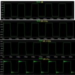
The Slew Rate with MIC is ~80Vus (Rise Time 0,75us).
The simulations in square wave (10Khz) has filter R-C input, but without output inductor.
Attachments
No, that peak is not OK in my opinion, and may be a red flag for local loop stability concerns. Something is going on there at 9MHz.
Cheers,
Bob
Hi Bob,
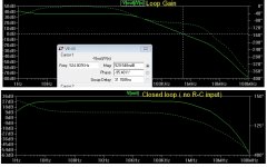
This is the same amp but now with predrivers compensated(RC to ground). Does this CLG could be read as stable? First one had PHM of 90 degree and GM of 13dB and this one PHM of 87 degree and GM of 16dB.
BR Damir
Attachments
One of the circuits has shunt capacitance at the output of the TIS.Thanks for this Michael.
I can't see any difference between the 2 circuits in that file.
Is this the sim of Bob's figs 3.13 you mention in #3172?
If this is investigating stability, leaving out his R6, the VAS emitter resistor, has a major effect.
The emitter resistor in the TIS reduces minor looop gain, but nowhere near enough to affect stability margins within the loop. Indeed, in this case, stability margins are worsened.
If you are just simulating his circuit, why not use Bob's devices and leave in the bits which affect stability, good or bad.The emitter resistor in the TIS reduces minor looop gain, but nowhere near enough to affect stability margins within the loop. Indeed, in this case, stability margins are worsened.
You can then compare the sims with his 'real life' results.
If you are recommending 'improvements', why not show your sim performance results to compare with his sims and also his 'real life' results.
If a sim shows a particular device change or 'improvement' results in worse performance/stability than a sim of something with known good 'real life' performance/stability, perhaps its a gentle hint from above not to move in that direction.
Why not start with something which works well in 'real life' and seems to tally with the sims?
______________
Can you post your plots which show 'minor loop is unstable'? Is that with the .ASC you posted in #3170?I have simulated your fig. 3.13 where the minor loop is unstable but did not see any sign of this in the closed loop frequency response of the amplifier.
Does this Closed Loop Gain look OK, ULGF is 720kHz?
Damir
I agree with Mr Cordell here, that doesnt look good at all, peaking looks in the region of 2db, my guess that circuit is either on the verge of oscillation or already oscillating. That plot looks like one taken from after the inductor, what does it look like before ?
- Home
- Amplifiers
- Solid State
- Bob Cordell's Power amplifier book