john curl said:filter on the output of the oscillator (thanks Scott Wurcer for that tip many years ago) and get a measurement of my amp into a 4 ohm load operating between 25-50W or so, wherever I can find a worse case in the region. I get a THD null from the Sound
You can actually do far better than a stock Audio Precision with just passive filtering on an old Sound Technology and good twin tee filters on the output of your amp, -140dB is doable with care. BTW John, that very same Sound Tech is sitting in a cube outside my office at this very moment. One of our interns was thrilled when I told him it was surplused.
Re: Distortion vs bias current
Hi Bob,
Very interesting and thought-provoking post and plot. Thanks very much for posting that.
Bob Cordell said:The plot below shows the crossover distortion spectra as a function of idle bias current for the Class-AB output stage with no negative feedback discussed earlier.
Hi Bob,
Very interesting and thought-provoking post and plot. Thanks very much for posting that.
Re: Re: Distortion vs bias current
Hi Jean-Pierre,
Thanks!
The transistor model I used is Andy_c's model. The NPN device is as follows:
.MODEL NJL3281DC npn IS=9.8145e-12 BF=438.0 NF=1.00 VAF=38 IKF=19.0 ISE=1.0e-12 NE=1.1237388682 BR=4.98985 NR=1.09511 VAR=4.32026 IKR=4.37516 ISC=3.25e-13 NC=3.96875 RB=3.997 RE=0.00 RC=0.06 XTB=0.115253 XTI=1.03146 EG=1.11986 CJE=1.144e-08 VJE=0.468574 MJE=0.34957 TF=2.6769e-9 XTF=7500 VTF=3.0 ITF=1000 CJC=1.093685e-9 VJC=0.623643 MJC=0.482111 XCJC=0.959922 FC=0.1 CJS=0 VJS=0.75 MJS=0.5 TR=1e-07 PTF=0 KF=0 AF=1 Vceo=200 Icrating=15 mfg=OnSemiconductor
Looks like RB is about 4 ohms and RE is zero.
I agree, there are numerous other interesting ways to look at this.
Cheers,
Bob
JPV said:
Great work! Difficult to minimize Spice after this.
First question wath are the base and emitter parasitic resistance in the model you have used?
According to Oliver's paper and using your data ( 85mA bias optimal) the Worse output voltage ( for distortion) should be a little more than 2 Volts.
An interesting view would be to plot the distortion curves with respect to i/Io where Iload = i+Io with gmRe as parameter.
Nice work
Jean-Pierre
Hi Jean-Pierre,
Thanks!
The transistor model I used is Andy_c's model. The NPN device is as follows:
.MODEL NJL3281DC npn IS=9.8145e-12 BF=438.0 NF=1.00 VAF=38 IKF=19.0 ISE=1.0e-12 NE=1.1237388682 BR=4.98985 NR=1.09511 VAR=4.32026 IKR=4.37516 ISC=3.25e-13 NC=3.96875 RB=3.997 RE=0.00 RC=0.06 XTB=0.115253 XTI=1.03146 EG=1.11986 CJE=1.144e-08 VJE=0.468574 MJE=0.34957 TF=2.6769e-9 XTF=7500 VTF=3.0 ITF=1000 CJC=1.093685e-9 VJC=0.623643 MJC=0.482111 XCJC=0.959922 FC=0.1 CJS=0 VJS=0.75 MJS=0.5 TR=1e-07 PTF=0 KF=0 AF=1 Vceo=200 Icrating=15 mfg=OnSemiconductor
Looks like RB is about 4 ohms and RE is zero.
I agree, there are numerous other interesting ways to look at this.
Cheers,
Bob
john curl said:Fellow designers, I would like to explain how I check my Parasound amps for minimum distortion.
First of all, I don't think that extremely high output levels are the most realistic place to evaluate an amp. Usually I chose an output level that will just show any significant distortion change, especially of higher order products. This is usually slightly above the rated class A region of the amp.
So, in the case of the JC-1:
It is typically operating about 25W class A into 8 ohms, so I might operate it at 25-50W into 4 ohms. This insures that I am in the class B region, and 4 ohms is always worse than 8 ohms in my amps.
I then set my Sound Technology 1700B to 5KHz, put a passive filter on the output of the oscillator (thanks Scott Wurcer for that tip many years ago) and get a measurement of my amp into a 4 ohm load operating between 25-50W or so, wherever I can find a worse case in the region. I get a THD null from the Sound Technology and I run it into my HP 3563 FFT analyzer to do a FFT of the results. I usually measure about 115dB down with the 7th harmonic (35KHz) in this case.
Personally I don't care much if the harmonic distortion, including 7th harmonic distortion tends to increase after 400W or so. It just has to meet THX, and there isn't much that I can do about it anyway, except to add some form of negative feedback. I don't like further stage complexity, so I tend to not do this.
For the record, please note the same distortion done by 'Stereophile' measuring the Halcro. It might be somewhat informative in this case.
Hi John,
Thanks for the explanation. This all seems pretty reasonable. Seventh harmonic of 5 kHz down 115 dB at 25-50 Watts into a 4 ohm load sounds pretty good as a target to shoot for.
Cheers,
Bob
Re: Re: Re: Distortion vs bias current
That's why I have chosen the 21193/4 model, which seems to me to be more realistic.
Bob Cordell said:
.RB=3.997 RE=0.00 RC=0.06
That's why I have chosen the 21193/4 model, which seems to me to be more realistic.
Re: Re: Re: Re: Distortion vs bias current
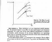
The base resistance is a hard one to get right. The plot below shows how a small RE value can mess up the determination of RB. Unfortunately, the data sheet info is not enough to distinguish the part of the errors due to RE and RB. So I've made the simplifying assumption that RE=0. This is described better here, about a third of the way down the page.
For example, if I had put RB=0 and RE=0.04, I would get similar results for the Ic vs. Vbe curves (with both fitting the datasheet well). I suspect the correct values are somewhere between the extremes of what I chose and the RB=0, RE=0.04 case.
The RC value matches the slope of the output curves in hard saturation to the datasheet. But if RE were greater than zero, RC would decrease by whatever RE ended up being.
I did get contact info from Charles for the project guys at OnSemi, but I have not contacted them yet. Maybe they have some insight as to what the real RE or RB is. Given one of these, I can compute the other from the deviation of ln(IC) vs. Vbe from a straight line. In that case, I could do a better parameter fit.
PMA said:That's why I have chosen the 21193/4 model, which seems to me to be more realistic.
The base resistance is a hard one to get right. The plot below shows how a small RE value can mess up the determination of RB. Unfortunately, the data sheet info is not enough to distinguish the part of the errors due to RE and RB. So I've made the simplifying assumption that RE=0. This is described better here, about a third of the way down the page.
For example, if I had put RB=0 and RE=0.04, I would get similar results for the Ic vs. Vbe curves (with both fitting the datasheet well). I suspect the correct values are somewhere between the extremes of what I chose and the RB=0, RE=0.04 case.
The RC value matches the slope of the output curves in hard saturation to the datasheet. But if RE were greater than zero, RC would decrease by whatever RE ended up being.
I did get contact info from Charles for the project guys at OnSemi, but I have not contacted them yet. Maybe they have some insight as to what the real RE or RB is. Given one of these, I can compute the other from the deviation of ln(IC) vs. Vbe from a straight line. In that case, I could do a better parameter fit.
Attachments
Bob Cordell said:For those of you who celebrate it, please enjoy a safe and happy Labor Day Weekend. I'll be out of contact for most or all of the weekend, up in Saratoga Springs NY at the lake.
Enjoy,
Bob
I just dropped my daughter off at Skidmore, maybe we should have an East Coast Burning Amp.

off topic
Hi John,
Rather confusing. Why don't make your coils from silver as well?
Cheers,
john curl said:[snip]
Actually, I use linear crystal 6 9's pure silver teflon coated wire in the Blowtorch preamp. It is VERY expensive and we have to break it in electrically in advance for weeks, and then again after we cut and solder it in. I have heard the difference between identical units, one made of the best oxygen free copper wire, and the silver wire.
[snip]
john curl said:I used to make MY coils from 14Ga oxygen free copper. So there!
Hi John,
Rather confusing.
Why don't make your coils from silver as well?Cheers,
- Home
- Amplifiers
- Solid State
- Bob Cordell Interview: Negative Feedback