Re: Re: Re: Output impedance of Hafler DH220
No, I don’t' believe so.
For the record, here is what I said on the topic before you mentioned the DH220 (taken from the MOSFET Vs BJT thread):
"Hi Bob
I’m continuing this discussion on output impedance from the closed down "audibility of output coils" thread here, since it is relevant to this thread.
I think 0.5uH is still a significant proportion of the total effective inductance, in the case that a small output coil is used to isolate a capacitive load.
Now how would that figure look if low transconductance Lateral MOSFET’s were used? Or if the bias current was lower (say 100mA) or if the MOSFET’s were driven directly from the VAS, as in probably 90% of MOSFET amplifiers ever made?
Cheers,
Glen"
And a subsequent post:
"OK, but a lot of people do advocate the use of low NFB. Low NFB in a low power amplifier (<~70W rms) with an output stage with an intrinsically high output impedance can quite easilly produce an amplifier with an equivalent output inductance in the uH range.
This is especially so in designs which drive a single pair of MOSFET's from a hot VAS. To match BJT performance in this regard, a driver stage and a decent bias current is pretty much mandatory.
Cheers,
Glen"
The DH220 may use Lateral MOSFET’s, but it uses two pairs in parallel. It is not a low feedback design and the MOSFET’s are not driven directly from the VAS, but from a complementary emitter folower driver stage.
Cheers,
Glen
Bob Cordell said:
Doing a little bit of back-peddling, Glen?
Cheers,
Bob
No, I don’t' believe so.
For the record, here is what I said on the topic before you mentioned the DH220 (taken from the MOSFET Vs BJT thread):
"Hi Bob
I’m continuing this discussion on output impedance from the closed down "audibility of output coils" thread here, since it is relevant to this thread.
I think 0.5uH is still a significant proportion of the total effective inductance, in the case that a small output coil is used to isolate a capacitive load.
Now how would that figure look if low transconductance Lateral MOSFET’s were used? Or if the bias current was lower (say 100mA) or if the MOSFET’s were driven directly from the VAS, as in probably 90% of MOSFET amplifiers ever made?
Cheers,
Glen"
And a subsequent post:
"OK, but a lot of people do advocate the use of low NFB. Low NFB in a low power amplifier (<~70W rms) with an output stage with an intrinsically high output impedance can quite easilly produce an amplifier with an equivalent output inductance in the uH range.
This is especially so in designs which drive a single pair of MOSFET's from a hot VAS. To match BJT performance in this regard, a driver stage and a decent bias current is pretty much mandatory.
Cheers,
Glen"
The DH220 may use Lateral MOSFET’s, but it uses two pairs in parallel. It is not a low feedback design and the MOSFET’s are not driven directly from the VAS, but from a complementary emitter folower driver stage.
Cheers,
Glen
Re: Re: Re: Re: Output impedance of Hafler DH220
Hi Glen,
You seem to have a basic misunderstanding of how MOSFET source followers behave. Paralleing MOSFETs does not generally reduce the output impedance of a source follower unless the TOTAL current is increased. The DH220 does not run its MOSFETs hot. If it only had a single pair of MOSFETs biased to the same total idle current, its output impedance would be relatively unchanged.
Indeed, the DH220 is a very basic, pedestrian version of a MOSFET amplifier, so it serves as a good example.
Cheers,
Bob
G.Kleinschmidt said:
No, I don’t' believe so.
For the record, here is what I said on the topic before you mentioned the DH220 (taken from the MOSFET Vs BJT thread):
"Hi Bob
I’m continuing this discussion on output impedance from the closed down "audibility of output coils" thread here, since it is relevant to this thread.
I think 0.5uH is still a significant proportion of the total effective inductance, in the case that a small output coil is used to isolate a capacitive load.
Now how would that figure look if low transconductance Lateral MOSFET’s were used? Or if the bias current was lower (say 100mA) or if the MOSFET’s were driven directly from the VAS, as in probably 90% of MOSFET amplifiers ever made?
Cheers,
Glen"
And a subsequent post:
"OK, but a lot of people do advocate the use of low NFB. Low NFB in a low power amplifier (<~70W rms) with an output stage with an intrinsically high output impedance can quite easilly produce an amplifier with an equivalent output inductance in the uH range.
This is especially so in designs which drive a single pair of MOSFET's from a hot VAS. To match BJT performance in this regard, a driver stage and a decent bias current is pretty much mandatory.
Cheers,
Glen"
The DH220 may use Lateral MOSFET’s, but it uses two pairs in parallel. It is not a low feedback design and the MOSFET’s are not driven directly from the VAS, but from a complementary emitter folower driver stage.
Cheers,
Glen
Hi Glen,
You seem to have a basic misunderstanding of how MOSFET source followers behave. Paralleing MOSFETs does not generally reduce the output impedance of a source follower unless the TOTAL current is increased. The DH220 does not run its MOSFETs hot. If it only had a single pair of MOSFETs biased to the same total idle current, its output impedance would be relatively unchanged.
Indeed, the DH220 is a very basic, pedestrian version of a MOSFET amplifier, so it serves as a good example.
Cheers,
Bob
Re: Re: Re: Re: Re: Output impedance of Hafler DH220
No, I do not have a misunderstanding (basic or otherwise) of how MOSFET source followers behave.
Lateral MOSFET designs (especially those of old) which do not employ active temperature compensation for the output devices typically bias each pair of MOSFET’s at the zero temperature coefficient point of Id vs Vgs. Paralleling Lateral MOSFET devices biased in such a manner does indeed lower the output impedance and scale the bias current proportionally.
In fact, this is exactly what is done in the DH-220. Service manual available here:
http://www.hafler.com/techsupport/pdf/DH-220_amp_man.pdf
The zero temp. coefficient point of Vgs for the 2SK134 / 2SJ49 Lateral MOSFET devices used in the DH-220 is approximately 100mA Id. According to the service manual, the DH-220’s bias current is set for a total positive rail quiescent current of 275mA per channel. The DH-220 clearly does run it’s output stages relatively hot (about 30W per channel) at a quiescent Id of approximately 100mA per device.
2SK134 data sheet here:
http://pdf1.alldatasheet.com/datasheet-pdf/view/63172/HITACHI/2SK134.html
Strangely, the biasing voltage for the MOSFET’s is developed across a Vbe multiplier in the DH-220, but the Vbe multiplier transistor (Q9) does not appear to be mounted on the heatsink, so it likely does not provide bias current temperature compensation for the MOSFET’s output devices themselves.
The DH-220 is complicated enough to include a complementary emitter follower driver for the MOSFET output stage with relatively high negative fedback throughout the audio band.
It is obviously not an example of the type of amplifier I claimed can have a high effective output inductance in the uH range.
Cheers,
Glen
Bob Cordell said:
Hi Glen,
You seem to have a basic misunderstanding of how MOSFET source followers behave. Paralleing MOSFETs does not generally reduce the output impedance of a source follower unless the TOTAL current is increased. The DH220 does not run its MOSFETs hot. If it only had a single pair of MOSFETs biased to the same total idle current, its output impedance would be relatively unchanged.
No, I do not have a misunderstanding (basic or otherwise) of how MOSFET source followers behave.
Lateral MOSFET designs (especially those of old) which do not employ active temperature compensation for the output devices typically bias each pair of MOSFET’s at the zero temperature coefficient point of Id vs Vgs. Paralleling Lateral MOSFET devices biased in such a manner does indeed lower the output impedance and scale the bias current proportionally.
In fact, this is exactly what is done in the DH-220. Service manual available here:
http://www.hafler.com/techsupport/pdf/DH-220_amp_man.pdf
The zero temp. coefficient point of Vgs for the 2SK134 / 2SJ49 Lateral MOSFET devices used in the DH-220 is approximately 100mA Id. According to the service manual, the DH-220’s bias current is set for a total positive rail quiescent current of 275mA per channel. The DH-220 clearly does run it’s output stages relatively hot (about 30W per channel) at a quiescent Id of approximately 100mA per device.
2SK134 data sheet here:
http://pdf1.alldatasheet.com/datasheet-pdf/view/63172/HITACHI/2SK134.html
Strangely, the biasing voltage for the MOSFET’s is developed across a Vbe multiplier in the DH-220, but the Vbe multiplier transistor (Q9) does not appear to be mounted on the heatsink, so it likely does not provide bias current temperature compensation for the MOSFET’s output devices themselves.
Bob Cordell said:
Indeed, the DH220 is a very basic, pedestrian version of a MOSFET amplifier, so it serves as a good example.
The DH-220 is complicated enough to include a complementary emitter follower driver for the MOSFET output stage with relatively high negative fedback throughout the audio band.
It is obviously not an example of the type of amplifier I claimed can have a high effective output inductance in the uH range.
Cheers,
Glen
Re: Re: Re: Re: Re: Output impedance of Hafler DH220
But if the DH-220 was built with only a single pair of 2SK134 / 2SJ49's in the output stage the total bias current would not be set to ~200mA, but to ~100mA, as it is in the DH-120. The DH-120 being the lower power version in only a single pair of the same MOSFETs in the output stage.
http://www.hafler.com/techsupport/pdf/DH-120_amp_man.pdf
Cheers,
Glen
Bob Cordell said:If it only had a single pair of MOSFETs biased to the same total idle current, its output impedance would be relatively unchanged.
But if the DH-220 was built with only a single pair of 2SK134 / 2SJ49's in the output stage the total bias current would not be set to ~200mA, but to ~100mA, as it is in the DH-120. The DH-120 being the lower power version in only a single pair of the same MOSFETs in the output stage.
http://www.hafler.com/techsupport/pdf/DH-120_amp_man.pdf
Cheers,
Glen
PMA said:100mA is too low value for power MOSFETs.
Well, if you wan't optimal bias current stability using fixed voltage biasing with the 2SK134 / 2SJ49 pair, about 100mA per device pair is what you need.
Cheers,
Glen
Upupa Epops said:BTW gentlemen, you are talking about Hafler's amps and their author is Erno Borbelly. Although he was long years my guru ( the same like Bob Cordell ), to this time I don't know his face. Have somebody his photo ? Thanks in advance...
Hi Upupa,
Look here:
http://www.borbelyaudio.com/about_us.asp
Cheers,
Re: Re: Re: Re: Re: Re: Output impedance of Hafler DH220
Hi Glen,
Is there a commercial design that represents what you were referring to, where we can have a look at the schematic here?
I'm sure there are many representative DIY designs.
Pete B.
G.Kleinschmidt said:
But if the DH-220 was built with only a single pair of 2SK134 / 2SJ49's in the output stage the total bias current would not be set to ~200mA, but to ~100mA, as it is in the DH-120. The DH-120 being the lower power version in only a single pair of the same MOSFETs in the output stage.
http://www.hafler.com/techsupport/pdf/DH-120_amp_man.pdf
Cheers,
Glen
Hi Glen,
Is there a commercial design that represents what you were referring to, where we can have a look at the schematic here?
I'm sure there are many representative DIY designs.
Pete B.
Re: Re: Re: Re: Re: Re: Output impedance of Hafler DH220
Hi Glen,
The Hafler is the most well-known MOSFET amplifier on the planet. Measurement if it is sufficient to blunt your overly-broad generalization about MOSFETs.
You will always be able to conjur up an example of where your assertion is correct. There are plenty of less-skilled designers out there who can screw up a perfectly good MOSFET amplifier to get the high output inductance scenario you mention, but there are just as many fools who can get terrible performance out of BJTs.
I thought we were here to discuss design tradeoffs among technologies that are applied with at least some amount of reasonable engineering.
Cheers,
Bob
G.Kleinschmidt said:
No, I do not have a misunderstanding (basic or otherwise) of how MOSFET source followers behave.
Lateral MOSFET designs (especially those of old) which do not employ active temperature compensation for the output devices typically bias each pair of MOSFET’s at the zero temperature coefficient point of Id vs Vgs. Paralleling Lateral MOSFET devices biased in such a manner does indeed lower the output impedance and scale the bias current proportionally.
In fact, this is exactly what is done in the DH-220. Service manual available here:
http://www.hafler.com/techsupport/pdf/DH-220_amp_man.pdf
The zero temp. coefficient point of Vgs for the 2SK134 / 2SJ49 Lateral MOSFET devices used in the DH-220 is approximately 100mA Id. According to the service manual, the DH-220’s bias current is set for a total positive rail quiescent current of 275mA per channel. The DH-220 clearly does run it’s output stages relatively hot (about 30W per channel) at a quiescent Id of approximately 100mA per device.
2SK134 data sheet here:
http://pdf1.alldatasheet.com/datasheet-pdf/view/63172/HITACHI/2SK134.html
Strangely, the biasing voltage for the MOSFET’s is developed across a Vbe multiplier in the DH-220, but the Vbe multiplier transistor (Q9) does not appear to be mounted on the heatsink, so it likely does not provide bias current temperature compensation for the MOSFET’s output devices themselves.
The DH-220 is complicated enough to include a complementary emitter follower driver for the MOSFET output stage with relatively high negative fedback throughout the audio band.
It is obviously not an example of the type of amplifier I claimed can have a high effective output inductance in the uH range.
Cheers,
Glen
Hi Glen,
The Hafler is the most well-known MOSFET amplifier on the planet. Measurement if it is sufficient to blunt your overly-broad generalization about MOSFETs.
You will always be able to conjur up an example of where your assertion is correct. There are plenty of less-skilled designers out there who can screw up a perfectly good MOSFET amplifier to get the high output inductance scenario you mention, but there are just as many fools who can get terrible performance out of BJTs.
I thought we were here to discuss design tradeoffs among technologies that are applied with at least some amount of reasonable engineering.
Cheers,
Bob
Re: Re: Re: Re: Re: Re: Re: Output impedance of Hafler DH220
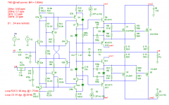
Or this one. It outperforms a blameless in many aspects, despite its simplicity.
Cheers,
Bob Cordell said:Hi Glen,
The Hafler is the most well-known MOSFET amplifier on the planet. Measurement if it is sufficient to blunt your overly-broad generalization about MOSFETs.
You will always be able to conjur up an example of where your assertion is correct. There are plenty of less-skilled designers out there who can screw up a perfectly good MOSFET amplifier to get the high output inductance scenario you mention, but there are just as many fools who can get terrible performance out of BJTs.
I thought we were here to discuss design tradeoffs among technologies that are applied with at least some amount of reasonable engineering.
Cheers,
Bob
Or this one. It outperforms a blameless in many aspects, despite its simplicity.
Cheers,
Attachments
Re: Re: Re: Re: Re: Re: Re: Output impedance of Hafler DH220
Excuse me? All I did was to highlight a rather specific set of design constraints which can result in an amplifier having a relatively high effective output inductance - namely relating to designs which drive the MOSFET's from a high impedance source (eg directly from the VAS) and/or use limited negative feedback.
What you provided is the measured results of an amplifier which doesn't qualify, followed by an accusation of “back-peddling” on my part. And now you characterise my specific statements pertaining to output impedance as “overly-broad generalisation about MOSFETs”. Give me a break.
There are many perfectly decent and competently designed MOSFET amplifiers in existence that drive the MOSFET’s directly from the VAS and/or use limited global negative feedback (especially not as high as 40dB at 20kHz). In fact, I’d say that the majority of MOSFET amplifiers designed and built by the DIY community would qualify as such, so I hardly see what is wrong with my attempt to raise the issues of these designs with respect to output impedance here at DIYaudio.
Such designs are the sole domain of fools according to you. Well fine, I’m sure others can decide on the merits of that declaration with out my need to comment.
Also, following my rebuttal, I notice that you’d rather not clarify any of your comments with regards to the biasing current/method used in the DH-220, or the alleged misunderstanding of how source followers behave on my part.
Thanks,
Glen
Bob Cordell said:
Hi Glen,
The Hafler is the most well-known MOSFET amplifier on the planet. Measurement if it is sufficient to blunt your overly-broad generalization about MOSFETs.
You will always be able to conjur up an example of where your assertion is correct. There are plenty of less-skilled designers out there who can screw up a perfectly good MOSFET amplifier to get the high output inductance scenario you mention, but there are just as many fools who can get terrible performance out of BJTs.
I thought we were here to discuss design tradeoffs among technologies that are applied with at least some amount of reasonable engineering.
Cheers,
Bob
Excuse me? All I did was to highlight a rather specific set of design constraints which can result in an amplifier having a relatively high effective output inductance - namely relating to designs which drive the MOSFET's from a high impedance source (eg directly from the VAS) and/or use limited negative feedback.
What you provided is the measured results of an amplifier which doesn't qualify, followed by an accusation of “back-peddling” on my part. And now you characterise my specific statements pertaining to output impedance as “overly-broad generalisation about MOSFETs”. Give me a break.
There are many perfectly decent and competently designed MOSFET amplifiers in existence that drive the MOSFET’s directly from the VAS and/or use limited global negative feedback (especially not as high as 40dB at 20kHz). In fact, I’d say that the majority of MOSFET amplifiers designed and built by the DIY community would qualify as such, so I hardly see what is wrong with my attempt to raise the issues of these designs with respect to output impedance here at DIYaudio.
Such designs are the sole domain of fools according to you. Well fine, I’m sure others can decide on the merits of that declaration with out my need to comment.
Also, following my rebuttal, I notice that you’d rather not clarify any of your comments with regards to the biasing current/method used in the DH-220, or the alleged misunderstanding of how source followers behave on my part.
Thanks,
Glen
Re: Re: Re: Re: Re: Re: Re: Re: Output impedance of Hafler DH220
So this is, along with the DH-220, is another design which negates my comments, as restated here: ????
http://www.diyaudio.com/forums/showthread.php?postid=1228856#post1228856
estuart said:Or this one.
So this is, along with the DH-220, is another design which negates my comments, as restated here: ????
http://www.diyaudio.com/forums/showthread.php?postid=1228856#post1228856
G.Kleinschmidt said:
Well, if you wan't optimal bias current stability using fixed voltage biasing with the 2SK134 / 2SJ49 pair, about 100mA per device pair is what you need.
Cheers,
Glen
I am more interested in sound quality and spectrum of distortion. From this point of view, higher bias current gives better results.
PMA said:
I am more interested in sound quality and spectrum of distortion. From this point of view, higher bias current gives better results.
Well that sounds plausible, but just out of curiosity do you design with lateral MOSFETs with a distinct Vgs/Id zero temperature coefficient characteristic and/or use bias current temperature compensation.
There is a lot of variation between different Lateral devices. Some parts such as the 2SK134 / 2SJ49 pair exhibit a distinct minimum temperature coefficient at a drain current of approximately 100mA. I’ve seen data sheets for some devices that are closer to 200mA. Then there are parts such as some of the Exicon Laterals which have excellent Vgs stability over temperature with any practical bias current below 200mA.
Then of course, there are Vertical MOSFETs, which generally exhibit distinct temperature stable Vgs at Id of several amps and make the use of temperature compensation circuitry mandatory.
Cheers,
Glen
PMA said:Thank you, I know the difference.
Geezzze. I'm sure you do and I'm not trying to imply otherwise.
You said that you prefer >100mA bias current for MOSFET's. Does that mean that you also prefer MOSFETs that are intrinsically more bias-current stable over temperature at bias currents above 100mA as well? Or do you prefer temperature compensation techniques? Or are you not particularly worried about a bit of bias current variation? These would all seem practically valid approaches to me.
Is this an unfair question to ask? If so, forgive me for attempting to discuss this issue in a bit more detail.

- Home
- Amplifiers
- Solid State
- Bob Cordell Interview: Negative Feedback