Graham Maynard said:Hi PMA,
I find it disconcerting that you argue against me and then post your own useful reverse driven amplifier investigations with a suddenly starting 10kHz sine.
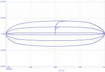
The first graph (class-AB) shows the applied current producing an initial error due to propagation delayed (C.dom or choke?) NFB control failing to maintain control, and then cycling with phase shift and showing crossover distortion.
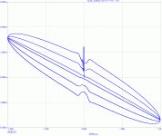
The second appears to have a good low output impedance damping of an initial sudden start (or is this bandwidth limited?)and a good damping phase response, though maybe not linear. The error amplitude appears to be approx 7mV (~ minus 66dB) for an equivalent of 16V at 8 ohms, though of course the amplifier output stage has it easy when it is merely attempting to maintain zero output volts.
Cheers ......... Graham.
Hi Graham,
I am sorry if my behaviour looked like you described, it was not my intention.
I posted the pictures to show the method that I found useful for evaluation of output stage crossover behaviour and its frequency dependence. When you plot these curves for increasing frequencies, you can see broadening in Y axis (lowering DF for higher freq.). The plots shown are for 10kHz. Accidentally the plots show initial transient as well, as the sine is started with zero voltage and current.
Best regards,
Pavel
Hi PMA,
You wrote >>Accidentally the plots show initial transient<<
Actually, the examination of that initial spike, although no signal will do this in real life, is an essential pointer as to how good the amplifier is likely to be !!!
Low bias amplifiers rely upon NFB to actively generate a low output impedance, and the initial spike of a suddenly starting 10kHz sine used to reverse drive the output teminal of an amplifier is an excellent way of examining NFB loop controlled amplifier capabilities.
The less the bias and the slower the amplifier (bandwidth) the higher/longer the spike.
Fast class-A amplifier spikes are more shallow and short, whilst of course the error curve is smooth due to lack of crossovers.
Also the nature of the spike on any reverse driven crossover error settlement inicates stability and speed of the NFB loop. A shallow or very quickly controlled class-AB spike could likely prove inaudible.
What is noticeable in your first plot is the amplitude asymmetry of the crossover plots arising long after the sudden start. I have outlined before that a leading back-EMF can reverse drive an output stage through a fraction of its output bias voltage at zero current crossovers before the NFB loop can re-establish control, and your first graph shows this happening.
The suddenly starting sine, whether forward or reverse, really is a good amplifier examining tool and there is nothing 'accidental' about it.
The second plot also concerns me because the error is greatest when the applied reverse drive passes through zero, the maximum rate of change !
A good amplifier plot ought to pass close to zero on this simple test, so here there is a loss of zero recovery or zero reference, possibly due to slewing inability or some form of feedback/feedforward control.
Cheers .......... Graham.
Hi Bob,
I have just gone back to the beginning of this thread (there is much in the middle I have not seen) and I smiled when I read your words >>
Much confusion originated here with Otala's mistaken assertion that one needed high open loop bandwidth to achieve low TIM (e.g., high slew rate). All else remaining equal, high open loop bandwidth has nothing to do with achievable slew rate or lower HF distortion.
So it all ends up being the philosophical choice of the designer, just like the choice of a designer as to whether he wants a no-feedback design, a design with modest feedback, or a design with high feedback. Since if there is feedback, it is often a function of frequency, one must be clear about what they mean when they say high or low feedback. Are they talking about NFB at 20 kHz, or are they talking about NFB at 1 kHz. <<
which brings us to the NFB amplifier's *loudspeaker* driving capabilities. I do not know if what you were talking about by Otala related to loudspeaker or resistor load based comment.
If there is not flat open loop gain to 20kHz when global NFB is isolated, then surely when NFB is connected its damping response will tend towards being in quadrature at that frequency and phase leading back-EMF error control cannot then be linear ?
Also there can be quite different loudspeaker driving behaviours relating to amplifier classes A and AB or bipolar/mosfet even though they might have the same bandwith/NFB characteristics when measured using a resistor load.
( There are so many balls an amplifier designer must keep in the air at the same time, lest he makes the proverbial !!!!! !! )
Cheers .......... Graham.
Re: Class-XD
Any particular reason why it's ''....not a favourite....''?
estuart said:.......such as two pole compensation (not a favorite of mine).......
Any particular reason why it's ''....not a favourite....''?
Re: Re: Class-XD
Hi Mike,
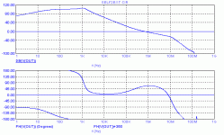
Look at the phase response of the global feedback loop and at the step response. That's why.
Cheers.
mikeks said:
Any particular reason why it's ''....not a favourite....''?
Hi Mike,
Look at the phase response of the global feedback loop and at the step response. That's why.
Cheers.
Attachments
Re: Re: Class-XD
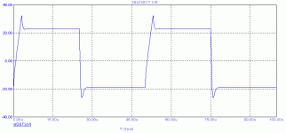
And here's the step response.
mikeks said:
Any particular reason why it's ''....not a favourite....''?
And here's the step response.
Attachments
Hi Edmond,
Whilst I have been critical of Douglas Self's approach in the past for ignoring the possibility of dynamic loudspeaker back-EMF causing 'crossover' distortion in a class-AB amplifier which uses high global NFB to give a very low THD amplifier, at least his XD arrangement is capable of preventing this at more critical / normal listening levels associated with quality auditioning.
Of course the crossover distortion can arise at higher listening levels once the offset current is overcome, but then the resulting distortion is much more likely to be masked by the music itself.
Mr Self still simulates for thd using only resistors though. Do you ?
Cheers ......... Graham.
Graham Maynard said:
Mr Self still simulates for thd using only resistors though. Do you ?
Hi Graham,
I simulated for thd as well as imd using nasty reactive loads too. Thus far, I encountered no problems.
Cheers,
Hi Nelson,
Quite so, but it will produce an individual sound that customers can -and do- like, and with the Patent, no one else can copy that 'sound'. Hi-Fi World did a review of an XD amplifier in their May 2006 issue. Of course their early sample could have been wrongly set up or their test bench different to what Cambridge and D Self uses, but the crossover distortion and its offset were clearly visible.
They did stress however, that there is much more to reproduced sound than crossover distortion and amplifier types, with which I must agree.
Will be back shortly to examine PMA's interesting reverse testing responses.
Cheers ........ Graham.
Attachments
mefistofelez said:Dear Pavel,
DPA 386se?
M
Dear Pavel,
nice to hear from you again.
It is PM-AB1, I think you know the amplifier quite well
PM
Nelson Pass said:I'm as much a fan of novelty as anyone, but it does strike me
that the idle dissipation of the XD amps is pretty high compared
to his previous work, and you could argue that a conventional
AB design at these idle levels would work equally well.

Hi Nelson,
I agree, maybe better.
Bob
- Home
- Amplifiers
- Solid State
- Bob Cordell Interview: Negative Feedback
