lumanauw said:The input differential pair is pair of Q201-Q202.
There are 2 sets of back to back diodes, one set is between the bases and another set is between the collectors.
Are these 2 sets = "soft clipping"?
It decreases gain of the differential stage affecting feedback, when overload protection starts working. Far from soft clipping.
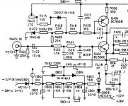
is this soft clipping? If the voltage is 28V (4ohm). Switch S801 is on (connected). Anode of D802 will be sitting at about -0V9 and katode of D804 sitting at +0V9.
If the dioda D802-D804 conduction is 0V6, then there is limit of -1V5 to +1V5
If the input signal at base of Q402 more positive than +1V5 or more negative than -1V5, then it will be "absorbed" by C410, signal bigger than +1V5 and smaller than -1V5 will not enter the Q402's base.
Is this soft clipping?
Attachments
It is kind of compressor, it adds distortions after output of the amp shows some voltage close to the certain level.
lumanauw said:is this soft clipping? If the voltage is 28V (4ohm). Switch S801 is on (connected). Anode of D802 will be sitting at about -0V9 and katode of D804 sitting at +0V9.
If the dioda D802-D804 conduction is 0V6, then there is limit of -1V5 to +1V5
If the input signal at base of Q402 more positive than +1V5 or more negative than -1V5, then it will be "absorbed" by C410, signal bigger than +1V5 and smaller than -1V5 will not enter the Q402's base.
Is this soft clipping?
Re: Re: Folded emitter followers
Adam,
One just has to be careful because the output is fed back to the collectors of the folded emitter followers with unity gain. At high frequencies the impedance of Ccb gets smaller. If that, in combination with some other reactive or peaking effects gets you close to positive feedback at high frequencies, you may have ringing or oscillation. It is a good exercise to SPICE this circuit. A very slight amount of LFP between the output node and the tied collectors of the folded EFs, done properly, can help. One also needs to be mindful of inductance in the base circuits of the folded EFs.
Bob
darkfenriz said:
I am not familiar with it in practice.
What is surprising or unexpected in HF behaviuor of this circuit?
regards
Adam
Adam,
One just has to be careful because the output is fed back to the collectors of the folded emitter followers with unity gain. At high frequencies the impedance of Ccb gets smaller. If that, in combination with some other reactive or peaking effects gets you close to positive feedback at high frequencies, you may have ringing or oscillation. It is a good exercise to SPICE this circuit. A very slight amount of LFP between the output node and the tied collectors of the folded EFs, done properly, can help. One also needs to be mindful of inductance in the base circuits of the folded EFs.
Bob
Importance of Damping Factor
Sometimes it is unfortunate that it is called damping factor, because that terminology tends to focus the issue too much on that one aspect you have mentioned here.
The real issue is that low damping factor implies relatively high output impedance. A classic vacuum tube amplifier, or even a solid state amplifier with no negative feedback, may only have a damping factor of 10. This corresponds to an output impedance of 0.8 ohms.
Now recognize that most loudspeakers have widely varying impedance as a function of frequency - not just in the bass region. It is not uncommon for a so-called 8-ohm speaker system to have a minimum impedance of 4 ohms and a maximum impedance of 40 ohms. Think about what this does to the final voltage frequency response as seen at the speaker terminals.
At places where the speaker impedance is actually the rated impedance of 8 ohms, we are down by about 1 dB as a result of the amplifier's 0.8 ohm output impedance against the 8 ohm load (relative to the amplifier's no-load output). At places where the speaker impedance is very high, we are down very little, so relatively speaking we are up 1 dB relative to the nominal. Where the speaker impedance dips to 4 0hms, we are down about a total of 2 dB, so we are down by 1 dB relative to the nominal. We thus have a frequency response swing of +/- 1 dB. This is definitely non-trivial.
Often, these large speaker impedance variations occur in the crossover region.
Cheers,
Bob
gerhard said:
I think this damping factor is pretty much overrated. The voice coil is accelerated and stopped by current (hopefuly, and as far as the amplifier is concerned), and an average 8 Ohm speaker has abt. 4-6 Ohm DC resistance. Now let your amplifier have 1 mOhm or 10 or 100 mOhm source impedance, -- it makes no difference. A value as bad as 100 mOhm would count as confession of incompetence.
regards, Gerhard
As a factoid, my B&W 804 S features 4.4 Ohms at DC (just checked), and although not measured myself, it won't drop below that over frequency IIR the data sheet correctly.
Sometimes it is unfortunate that it is called damping factor, because that terminology tends to focus the issue too much on that one aspect you have mentioned here.
The real issue is that low damping factor implies relatively high output impedance. A classic vacuum tube amplifier, or even a solid state amplifier with no negative feedback, may only have a damping factor of 10. This corresponds to an output impedance of 0.8 ohms.
Now recognize that most loudspeakers have widely varying impedance as a function of frequency - not just in the bass region. It is not uncommon for a so-called 8-ohm speaker system to have a minimum impedance of 4 ohms and a maximum impedance of 40 ohms. Think about what this does to the final voltage frequency response as seen at the speaker terminals.
At places where the speaker impedance is actually the rated impedance of 8 ohms, we are down by about 1 dB as a result of the amplifier's 0.8 ohm output impedance against the 8 ohm load (relative to the amplifier's no-load output). At places where the speaker impedance is very high, we are down very little, so relatively speaking we are up 1 dB relative to the nominal. Where the speaker impedance dips to 4 0hms, we are down about a total of 2 dB, so we are down by 1 dB relative to the nominal. We thus have a frequency response swing of +/- 1 dB. This is definitely non-trivial.
Often, these large speaker impedance variations occur in the crossover region.
Cheers,
Bob
Re: Importance of Damping Factor
Isn't the room influence much larger than that? I suppose you could hear the same difference in sound between your MOSFET and KT88 amps in every room you listened to them and probably even with different loudspeakers?
Bob Cordell said:
... We thus have a frequency response swing of +/- 1 dB. This is definitely non-trivial.
Often, these large speaker impedance variations occur in the crossover region.
Cheers,
Bob
Isn't the room influence much larger than that? I suppose you could hear the same difference in sound between your MOSFET and KT88 amps in every room you listened to them and probably even with different loudspeakers?
PMA said:Bob,
for this class A push-pull output stage with strong local feedback, the output impedance was 0.1 ohm.
Cheers,
Pavel
Do you mean 0.05 Ohm?
Wavebourn said:
Do you mean 0.05 Ohm?
In theory, almost yes. Simulation showed 0.07 ohm. But amp was built and had been operated for 2 years. Measurements showed damping factor 80 at 8 ohm load.
Hi Wavebourn,
I like your input limiter with indicator. However I think it would be a nice idea as for any clipping indicator to add some kind of monostable at the op-amp output. It would make the LED lighting last longer than the clipping (say 1/10 s) and would show how we can often be unaware of short clipping. Without monostable, the LEDs may flash so shortly that it remains almost invisible.
I like your input limiter with indicator. However I think it would be a nice idea as for any clipping indicator to add some kind of monostable at the op-amp output. It would make the LED lighting last longer than the clipping (say 1/10 s) and would show how we can often be unaware of short clipping. Without monostable, the LEDs may flash so shortly that it remains almost invisible.
As Bob said, some of the best sounding amps have output resistance as high as 0.8 ohms. Look at Audio research's website for proof. I would be very careful not to compromise more important design parameters in the pursuit of diminishingly small output resistance, if sound quality is your primary goal.
forr said:Hi Wavebourn,
I like your input limiter with indicator. However I think it would be a nice idea as for any clipping indicator to add some kind of monostable at the op-amp output. It would make the LED lighting last longer than the clipping (say 1/10 s) and would show how we can often be unaware of short clipping. Without monostable, the LEDs may flash so shortly that it remains almost invisible.
I did before, but later found that it's practically enough without any capacitors/latches/monostables. Short flashes of high intensity red LEDs are well visible.
mikeks said:You appear to imply a correlation between relatively high output resistance and perceived ''sound quality''.
This is misplaced.
If both qualities correlate with the third one that is the cause, may we say that they are correlated?
It is possible to have good sound with .8 ohm output resistance. In fact, the original AR-1 loudspeaker originally had a recommended damping factor of 1. I experimented with this over 40 years ago and found this to be true. Variable damping factor can be designed into power amps, but we usually default today to high damping factor just to give a consistant standard to work with by the loudspeaker manufacturers.
Personally, I have to add .3-.5 ohms in series with my amps in order to drive my WATT 1 loudspeakers. These speakers drop their impedance to about .5 ohm at 2KHz. This is a design compromise that I must live with. Adding the resistor does not effect the sound very much, thank goodness.
Personally, I have to add .3-.5 ohms in series with my amps in order to drive my WATT 1 loudspeakers. These speakers drop their impedance to about .5 ohm at 2KHz. This is a design compromise that I must live with. Adding the resistor does not effect the sound very much, thank goodness.
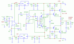
Passive Adaptive Soft Clip Circuit
I don't have a drawing right now. This circuit employs diodes in both directions shunting the input signal after it has passed through a 1 K resistor. Each diode is returned to a source of reverse bias of the appropriate polarity. The magnitude of the reverse bias is arrived at by filtering the power supply rail quite well, scaling it down to an appropriate level (with a calibration adjustment), and subtracting off a diode drop. This results in purely passive clipping action, the onset of which adapts to the available rail voltage. This results in soft clipping that does not compromize significantly the dynamic headroom of the amplifier.
The diodes are realized with the collector-base junction of a 2n3904 transistor (base and emitter shorted).
In practice, the calibration pot is first set to provide a fairly high clip threshold. The amplifier is then driven just barely into clipping into an 8 ohm load. The pot is then adjusted so that the soft clip circuit just starts clipping before the amplifier itself, as seen on an oscilloscope.
Bob
lumanauw said:
Hi, Bob Cordell,
Thanks for the info
What is a soft clip cct in input of feedback amp looks like? Do you have a drawing of this?
I don't have a drawing right now. This circuit employs diodes in both directions shunting the input signal after it has passed through a 1 K resistor. Each diode is returned to a source of reverse bias of the appropriate polarity. The magnitude of the reverse bias is arrived at by filtering the power supply rail quite well, scaling it down to an appropriate level (with a calibration adjustment), and subtracting off a diode drop. This results in purely passive clipping action, the onset of which adapts to the available rail voltage. This results in soft clipping that does not compromize significantly the dynamic headroom of the amplifier.
The diodes are realized with the collector-base junction of a 2n3904 transistor (base and emitter shorted).
In practice, the calibration pot is first set to provide a fairly high clip threshold. The amplifier is then driven just barely into clipping into an 8 ohm load. The pot is then adjusted so that the soft clip circuit just starts clipping before the amplifier itself, as seen on an oscilloscope.
Bob
- Home
- Amplifiers
- Solid State
- Bob Cordell Interview: Error Correction