I wrote:
I haven't made a case yet. I casually threw out some things that my personal experience guides me to examine of any amplifier design. Whether they matter or not with your circuit is yet to be argued, let alone agreed and this is why I'm doing so much work to understand it. My interest at the outset is distortion and sound quality rather than material or manufacturing cost. Others may want to steer things differently.
I should have written:What I don't really like on the face of it is...
Sorry, Bob, if I was overly-presumptuous. I have no intention of questioning the stature of your 1984 design. No at all. I have said I think I might be able to improve upon it and that is presumptuous. The purpose is learn something in the process and have some fun debates.On the face of it, the areas I think might be improvable are...
I haven't made a case yet. I casually threw out some things that my personal experience guides me to examine of any amplifier design. Whether they matter or not with your circuit is yet to be argued, let alone agreed
and this is why I'm doing so much work to understand it. My interest at the outset is distortion and sound quality rather than material or manufacturing cost. Others may want to steer things differently.traderbam said:Andy,
Thanks for that clarification and thanks for those old datasheets. Hope your scanner didn't get clogged up with dust. Those bipolars are pretty darned speedy.
You're welcome, Brian. I was surprised at how fast those parts were also. If you end up using KSA1220A and/or KSC2690A, I have a fix for the problem with their SPICE models incorrectly reporting nearly 1 GHz fT.
Can we get some discussion of feedforward EC? I don't remember seeing any discussion of it in this thread, or practical examples anywhere else.Bob Cordell said:This is even true for feedforward error correction.
Andy_c wrote:
Andy, I have no candidates yet. If you think those are good then please send me your models. BTW you are more experienced than I in models...is it possible to tweak existing ones? Specifically, the IRF7401/7404 are good matches wrt gm but their capacitances are about twice as large as the IRF132/9130.You're welcome, Brian. I was surprised at how fast those parts were also. If you end up using KSA1220A and/or KSC2690A, I have a fix for the problem with their SPICE models incorrectly reporting nearly 1 GHz fT.
Mikeks wrote:
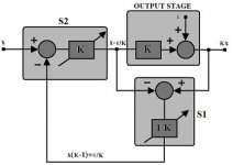
I've posted what I think is the diagram you are talking about and the loop gain equation you said was: K + e - 1. This is what I asked you to do many pages back. If these aren't right then please post whatever it is you are talking about.
This diagram is not Hawksford's model but is similar.
I am at a loss as to why you can't see the PFB loop with infinite gain around S1 and S2. Similarly the NFB loop gain is infinite.
Your node equations are only correct, in stable equilibrium, if the error term e is zero or is independent of all other node values, ie: the system is linear.
Hawksford was careful not to make this assumption. He represented his output stage as a non-linear function N. He called the input to N, Vn, and the output N(Vn). To find Vn you have to say Vn = Z(Kx) where Z is the inverse function of N defined by Z(N(x))=x. Hawsford avoided solving Vn at all - in fact he simply ingored it and assumed it was whatever it needed to be for the output to equal the input. This is why Hawksford's system is impossible to implement when a=1, b=0.
Hawksford is a negative feedback loop without any positive feedback
I've posted what I think is the diagram you are talking about and the loop gain equation you said was: K + e - 1. This is what I asked you to do many pages back. If these aren't right then please post whatever it is you are talking about.
This diagram is not Hawksford's model but is similar.
I am at a loss as to why you can't see the PFB loop with infinite gain around S1 and S2. Similarly the NFB loop gain is infinite.
Your node equations are only correct, in stable equilibrium, if the error term e is zero or is independent of all other node values, ie: the system is linear.
Hawksford was careful not to make this assumption. He represented his output stage as a non-linear function N. He called the input to N, Vn, and the output N(Vn). To find Vn you have to say Vn = Z(Kx) where Z is the inverse function of N defined by Z(N(x))=x. Hawsford avoided solving Vn at all - in fact he simply ingored it and assumed it was whatever it needed to be for the output to equal the input. This is why Hawksford's system is impossible to implement when a=1, b=0.
Attachments
traderbam said:Mikeks wrote:
I've posted what I think is the diagram you are talking about and the loop gain equation you said was: K + e - 1. This is what I asked you to do many pages back. If these aren't right then please post whatever it is you are talking about.
For the umpteenth time:

http://www.diyaudio.com/forums/showthread.php?postid=1069141#post1069141
http://www.diyaudio.com/forums/showthread.php?postid=1070832#post1070832
traderbam said:
This diagram is not Hawksford's model but is similar.
With this statement, Brian, you've demonstrated that you really have no idea what is going on.
traderbam said:Similarly the NFB loop gain is infinite.
No.
traderbam said:
Your node equations are only correct, in stable equilibrium, if the error term e is zero or is independent of all other node values, ie: the system is linear.
No.
traderbam said:
This diagram is not Hawksford's model but is similar.
With this statement, Brian, you've demonstrated that you really had no idea what is going on all along.
traderbam said:Similarly the NFB loop gain is infinite.
No.
traderbam said:Hawksford was careful not to make this assumption. He represented his output stage as a non-linear function N.
No.
traderbam said:This is why Hawksford's system is impossible to implement when a=1, b=0.
If this statement is true, then it implies that Cordell's design never existed.

Brian, i have now retired from ALL your posts.
Re: Re: Re: Re: Re: Give SPICE a try (& HF Ingress)
The L-R combinations I mentioned will keep you out of trouble insofar as amplifier stability, but the amount by which they may cause ringing into a purely capacitive load will vary depending on the load. If you have a particular load in mind, I suggest experimentation with square waves and a scope or SPICE. The good news is that if you are always going to be feeding a particular load, you can incorporate that load's characteristics into what would amount to a specific form of second-order low pass filter, possibly even with no ringing at all. You might even be able to use a filter program in this context.
Bob
Nixie said:
Thanks for the reply. What about purely capacitive load? I have an amp direct-driving electrostatic headphones (~1500 V differential p-p into a hundred or so pF load). What would seem an appropriate filter for such a case?
The L-R combinations I mentioned will keep you out of trouble insofar as amplifier stability, but the amount by which they may cause ringing into a purely capacitive load will vary depending on the load. If you have a particular load in mind, I suggest experimentation with square waves and a scope or SPICE. The good news is that if you are always going to be feeding a particular load, you can incorporate that load's characteristics into what would amount to a specific form of second-order low pass filter, possibly even with no ringing at all. You might even be able to use a filter program in this context.
Bob
andy_c said:
Mike, I think I've mentioned this before, but traderbam is talking about the outer loop in the path containing the output stage. This loop looks more like a normal feedback loop, whose loop gain seems to correlate with the amount of distortion reduction. Its prpoerties also lend themselves to normal analysis methods of gain and phase margin for looking at loop stability. The inner loop, with its low loop gain, doesn't seem to lend itself well to these traditional stablity measures. Try it with the loop gain probe. You'll see the high loop gain in the outer loop.
Andy, I agree.
Bob
Bob Cordell said:Andy, I agree.
Bob
Well, if you agree, what do you think of this?
traderbam said:Similarly the NFB loop gain is infinite.
Nixie said:
Can we get some discussion of feedforward EC? I don't remember seeing any discussion of it in this thread, or practical examples anywhere else.
Read up on the Quad current-dumping amplifier.
Bob
mikeks said:
Well, if you agree, what do you think of this?
If you look at HEC as a NFB system in disguise, and you look at the outer loop, yes, the loop gain appears to head toward infinity, at least at low frequencies where component values are perfect and it is assumed that we are looking at the small-signal case, where nonlinearities do not come into play in the analysis.
I believe that in an HEC circuit, you should always be able to find a PFB loop by proper block diagram manipulation.
None of this takes away from the elegance and effectiveness of the circuit, and it does not, in my view, make it wrong to characterize the behavior of the circuit as that of error correction.
Bob
Bob Cordell said:If you look at HEC as a NFB system in disguise, and you look at the outer loop, yes, the loop gain appears to head toward infinity....
Bob
This, at balance, is factually incorrect in all respects: see last sentence on page 3 here.
Indeed, your figure 11 here is a complete disproof of your statement above.
Hawksford had in the tiltle of his 1981 paper "distortion correction". In the body he talks about feedback and feedforward correction and under section 1 calls the combined system a "distortion cancellation technique". In section 2 entitled "circuit topologies for output stage linearization" he refers to "distortion correction feedback". Bob, your paper uses the term "error correction".
So it seems that there is much variety in the naming of related concepts.
At the conceptual level, or theoretical level if you will, the functionality between Hawksford (feedback correction, b=0) and a NFB loop is identical. There are always many different ways to implement the same thing but I don't understand how these various names distiguish among different implementations.
I notice Bob's circuit, which is based on Hawksford's fig 5, is not a direct implemenation of the model (so Hawksford's own fig 5 is not quite the same as his conceptual model). It uses an extra NFB loop from the gates and this creates a different response than the model with a=1. It's functionality is different to fig 5 which has a different connection on the lower half.
Bob, you are very clear about calling your circuit "error correction". Could you define this term so that we can decide whether a particular feedback system implementation qualifies as "error correction"?
Upupa Epops said:......somewhere in your bench is the best amp of all time...
Who am i to disagree.
Just kidding.

- Home
- Amplifiers
- Solid State
- Bob Cordell Interview: Error Correction