john curl said:It isn't that different. I have designed both high negative feedback and no loop feedback preamps in the last 5 years with essentially the same parts and topology. It seems pointless to add a feedback loop to a line preamp, IF you do it with a lot of care.
I don't know what to say about power amps, except that low feedback usually means high open loop bandwidth, and I think that is the most important factor.
While Charles, Nelson, and I tend to make open loop designs on occasion, this does not mean that Matti Otala ever said that negative feedback was forbidden in a quality design. I have one of his power amps and it has a negative feedback loop. The amp that he made for HK in 1980 had loop feedback, so I find that a lot of criticism of Matti is not based on much evidence.
What Matti promoted was high open loop bandwidth and high slew rate. This approach has been successful for me, ever since I first made the JC-2 line amps in 1973.
Our original work on TIM did not 'prove' that high open loop bandwidth was desirable or necessary. PIM tends to show that high open loop bandwidth is desirable, and maybe even necessary in the best designs.
John, be careful about re-writing history. Matti Otala never used the word "slew rate" in any of his publications until a large number of us in the audio business pointed out that he had merely re-invented slew rate distortion. Even Barrie Gilbert in the article you like to cite pointed out that Otala re-discovered slew rate distortion (and this definitely includes distortion that occurs below slew rate as slew rate is approached). You and I both know that Matti was, at the time, a very electro-political being.
If he didn't know about slew rate in amplifiers before it had to be pointed out to him, he should have known better, being the very well-read and intelligent person that he is.
If he did know about slew rate during the time of his TIM publications, then one can only speculate on his motive for not referring to the term in his writings. Kind of like when you file for a patent, you are supposed to disclose prior art.
For a given gain-crossover frequency, PIM arising from the application of NFB is essentially the same whether the open-loop bandwidth is high or low. Take a look at my PIM paper on my web site at www.cordellaudio.com for the details.
Have you measured PIM? I'd be interested in how you did it and what your results were. Maybe they were different from mine.
Bob
andy_c said:......
But achieving this condition carries a high cost - namely throwing away a lot of open-loop gain to get there. .....
Andy
While you can count me in the camp of GNF believers, we should also recognize there is a matter of balance involved.
We start with a given amount of say, THD, for the sake of focusing on an issue, and apply a certain amount of attenuation in the form of OL to CL gain tradeoff. This will provide a new an lower level of THD.
The same result could be attained starting with a lower amount of THD (because of clever design) and a lower OL to CL attenuation margin.
What I mean is OL gain per se is not - at least as I see it - an goal in itself but a means to an end as far as the overall result - hitting the best possible combination of starting THD and available correction to obtain the minimum THD within the given design constraints.
Rodolfo
PS.
On the other hand I will readily go for maximum OL gain if it can be proved in a reasonably general way that the optimum global result is allways to be found at the maximum gain extreme.
andy_c said:Pavel, if you're interested in the formulas, I can put something up on my web pages this weekend.
Andy,
for sure, and also results of simulations of PIM are of a great interest.
THX,
Pavel
Bricolo said:
1kHz OL bandwidth. So you're not believing in high open loop bandwidth for good sound? That seems contrary to what Mr Curl and Ottala believe.
What's the reason, what's your belief?
You are correct, I do not believe that high open loop bandwidth is either necessary or sufficient for good sound. And that position is indeed contrary to the beliefs of John Curl and Matti Otala.
All of the technical reasons given as to why wide open-loop bandwidth should result in a better sounding amplifier, such as TIM and PIM, have proven to be unfounded when properly investigated by measurement. I know that this tends to be counter-intuitive, but these are not the only things in audio and electronics that are counter-intuitive.
Here's another thing to consider: The Analog Devices AD797 is one of the very best audio op amps available. It is known intimately by Barrie Gilbert and Walt Jung, both of whom work at ADI. It has an open-loop bandwidth of less than 200 Hz. Food for thought...
Cheers,
Bob
traderbam said:[snip]....these all seem perfectly valid ways to describe different distortion presentations to me. Why not?
No problem, indeed. Unless you want to communicate with others, of course.
Jan Didden
PMA said:I do not understand these grapes of wrath, it would be much easier and better to show measurements (or formulae and calculations) supporting written assumptions.
simulation should be even more accessible than equations for amp builders - after all schematics and waveforms are even closer to real world implementations, spice models are limited but often include many more effects than most mathematical analysis
jcx said:Simple Miller Compensated Voltage Amp test circuit,
Right circuit high loop gain, left low gain – 10 KOhm R6 resistive local VAS feedback lowering open loop gain to ~20 dB, same GBW as high gain
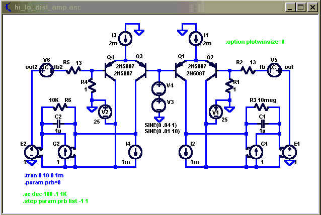
loop gain plots green high gain, red low gain ( V5,6 are 1 V AC sources for the loop gain plot )
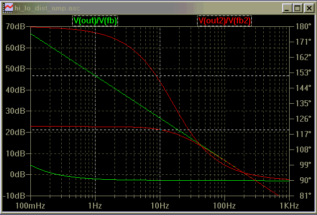
2 tone 4:1 1,10 Hz distortion spectrum, 0.5 V peak input signal amplitude; green high gain, red low
(4:1 amplitude ratio for lo:hi frequency components is commonly used since it is assumed that low frequencies will typically be larger in amplitude; music is commonly asserted to have ~ 3KHz power bandwidth)
same with only 0.05 V peak input signal amplitude; green high gain, red low - shows scaling of distortion products follows theory, 20 dB less signal amplitude, 60 dB less distortion product ( but dist/signal ratio improves 40 dB as previously discussed)
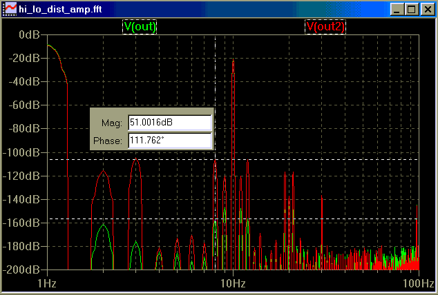
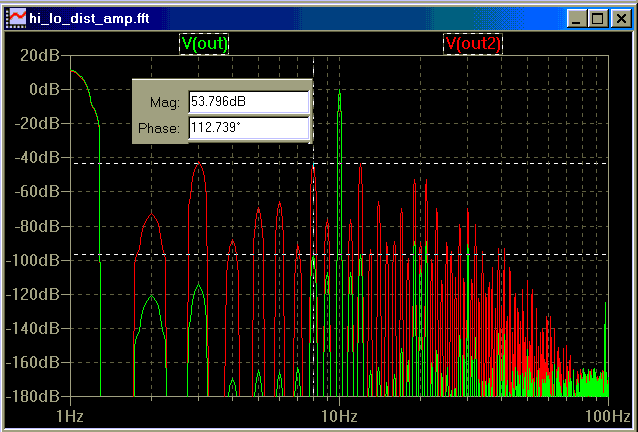
the major distortion source is the tanh nonlinearity of the diff input transistors, to focus on this effect consider the 8 Hz IM product from the dominant 3rd order nonlinearity (10 Hz - 2* 1 Hz )
in the distortion spectrum plots we see >50 dB more of this IM distortion product with the low gain amp (red) than in the high loop gain amp, looking at the phase diff from the cursor diff inset we also see that the green and red 8 Hz IM products differ in phase by 112 dgrees ~= the 90 degree phase diff characteristic of FM vs AM modulation products I showed in post # 80 – presumably the green is nearly pure “FM” modulation type distortion
this sim illustrates why some of us have a hard time accepting the low gain/high bandwidth approach – the high gain approach will always have less differential input signal amplitude at low frequencies which hugely reduces the distortion amplitude in the bjt diff pair – FM/PIM distortion would have to be shown to be orders of magnitude more objectionable than AM IM products for an engineer to choose to lower open loop gain at low frequencies to change the phase relations of the IM distortion products from that characterized as “FM” modulation distortion to the supposedly less objectionable “AM” IM distortion product phase relationship
circuit is frequency scaled to eliminate any nonlinear C effects, to look at just the input pair tanh distortion
mlloyd1 said:hey bob:
now that you had a few years to ponder, what changes would you make to your 50w errror correcting mosfet amp if you were designing/building it today?
mlloyd1
I'd change my name to Halcro and make a bunch of money
") .
.Just kidding.
Actually, I've been pondering just that question over the last year or so. It is always a good thing to reflect, and its is always a fun thing to take into account new technology or improvements in technology.
I've considered many different input-stage/VAS topologies along the way, but I keep coming back to essentially the one I published. Of course, some evolutionary changes can be made in it.
I would probably aim for a design that does about 150 watts/channel.
I would use faster transistors in the driver and error-correcting stage. I have also built MOSFET power amplifiers with folded emitter followers driving the power MOSFETs, and I like how this topology performs.
I'd still use an output inductor, but it would probably be an air-core torroidal inductor.
I would incorporate a passive-adaptive soft clipping circuit at the input.
I would build it on a 4-layer printed wiring board.
Thanks for your interest.
Bob
PMA said:I do not understand these grapes of wrath, it would be much easier and better to show measurements (or formulae and calculations) supporting written assumptions.
Pavel, I agree. Indeed, with formulas and calculations we can still get into trouble if we do not verify their results through measurements. Formulas and calculations alone are always vulnerable to wrong assumptions and outright mistakes. There is a lot of what you seek on this subject on my web site at www.cordellaudio.com in the published papers section - theory, explanation, calculation and measurements.
Cheers,
Bob
jcx said:
simulation should be even more accessible than equations for amp builders - .....
jcx, I was pretty well aware of your earlier simulations, but you must admit the only source of nonlinearity in this case is the tanh input differential, being all other components ideal.
In this case it could probably have been said beforehand the best tradeoff is maximum OL gain, since this way we get at the same time the smallest nonlinear operation range and the maximum feedback correction factor, i.e. the best of both worlds.
My concern is how much this translates to a practical realization. If it can be proved allways possible, then I abide by my previous PS, I go for maximum OL gain.
Rodolfo
ingrast said:
Andy
While you can count me in the camp of GNF believers, we should also recognize there is a matter of balance involved.
We start with a given amount of say, THD, for the sake of focusing on an issue, and apply a certain amount of attenuation in the form of OL to CL gain tradeoff. This will provide a new an lower level of THD.
The same result could be attained starting with a lower amount of THD (because of clever design) and a lower OL to CL attenuation margin.
What I mean is OL gain per se is not - at least as I see it - an goal in itself but a means to an end as far as the overall result - hitting the best possible combination of starting THD and available correction to obtain the minimum THD within the given design constraints.
Rodolfo
PS.
On the other hand I will readily go for maximum OL gain if it can be proved in a reasonably general way that the optimum global result is allways to be found at the maximum gain extreme.
Rodolfo,
You have put it very well. Indeed we should always strive for the most linear open loop amplifier before we put feedback around it. Similarly, we should never add to, or increase, open-loop gain at the expense of linearity or high-frequency excess phase.
It often turns out that having greater open-loop gain at frequencies below 20 kHz does not at all conflict with these other goals. In fact, some approaches to arriving at less open-loop gain at frequencies below 20 khz (so as to arrive at higher open-loop bandwidth) will actually compromize linearity. The simplest example of such a foolish approach is to add load resistors to the output of the VAS. Make the VAS work harder driving a load and it will create more distortion.
Cheers,
Bob
lumanauw said:
I could be wrong, but I think it is the Electrocompaniet 25W classA
I don't see how it is possible to apply global feedback to this monster and avoid oscillations.
traderbam said:Barrie's analysis is only about input stage distortion. The reality is way different so the importance of loop gain to correct downstream errors is even more critical.
I'd definitely agree with that. If the open-loop amplifier were assumed to have non-zero intrinsic PIM, it's a good bet that the high DC open-loop gain, narrow open-loop bandwidth alternative would have less closed-loop PIM than the wide open-loop bandwidth alternative. I don't know of any way to analyze or simulate this though, because I don't know of any way to separate the distortion due to AM-to-AM from that due to AM-to-PM in the simulator. My previous comments should only be taken in the context of Barrie's article and not the much more complex real world case.
Practical measurement of PIM
I would be interested how to measure the PIM in the real circuit. The AD797 was mentioned here. There are several opamps even better "to my ears" , one of them is OPA627. The problem is, that I am quite unable to measure distortion of this opamp, as the ICs used in my FFT analysis have worse parameters. I would appreciate any hint how to measure the PIM of the OPA627.
I would be interested how to measure the PIM in the real circuit. The AD797 was mentioned here. There are several opamps even better "to my ears"
, one of them is OPA627. The problem is, that I am quite unable to measure distortion of this opamp, as the ICs used in my FFT analysis have worse parameters. I would appreciate any hint how to measure the PIM of the OPA627.One of the examples of my measurements is here (audio buffer):
http://web.telecom.cz/macura/buf.jpg
The THD measured (0.00048%) is that of the method, not the audio buffer.
With notch filter, we got 0.000077%. Again, limitation of the method.
http://web.telecom.cz/macura/buf.jpg
The THD measured (0.00048%) is that of the method, not the audio buffer.
With notch filter, we got 0.000077%. Again, limitation of the method.
I'd disagree with this if it were meant as a blanket statement. It depends on the control system.Indeed we should always strive for the most linear open loop amplifier before we put feedback around it. Similarly, we should never add to, or increase, open-loop gain at the expense of linearity or high-frequency excess phase.
Bob Cordell said:
You are correct, I do not believe that high open loop bandwidth is either necessary or sufficient for good sound. And that position is indeed contrary to the beliefs of John Curl and Matti Otala.
All of the technical reasons given as to why wide open-loop bandwidth should result in a better sounding amplifier, such as TIM and PIM, have proven to be unfounded when properly investigated by measurement. I know that this tends to be counter-intuitive, but these are not the only things in audio and electronics that are counter-intuitive.
Here's another thing to consider: The Analog Devices AD797 is one of the very best audio op amps available. It is known intimately by Barrie Gilbert and Walt Jung, both of whom work at ADI. It has an open-loop bandwidth of less than 200 Hz. Food for thought...
Cheers,
Bob
I'm sorry if the answer is in one of your papers, just tell me if it's the case. I'll definitely have to read them soon.
If high OL bandwith isn't necessary, so what is? What are the guidelines to design an amp with low TIM/PIM/etc distortion? Are there any papers about this?
PS: what do you call folded emitter followers?
- Home
- Amplifiers
- Solid State
- Bob Cordell Interview: Error Correction