Interesting. I know nothing about any of this, but I would be a little cautious. To my untrained eyes, these are not the same as the ones in the Carverfest pictures.
It does seem surprising to me that the case is a simple aluminum box, the components look fairly low end, although the wiring and turrets look great. I am also a little surprised at the binding posts. Looks like they are from the same place as the volume knob.
i know not all greats and gurus feel strongly about audiophlia and the fancy stuff, but this seems off, not having seen the back of a carver amp to see what he used. Anyway, for the price, i personally would like more of a guarantee that this is actually Carver, then I can trust the components more.
You are correct,, the ones in the pictures are a few iterations back,, these are what he's currently building,,we'll probabally see them at this years fest.
I had correspondence with him about a year ago regarding the "6AL5 DC restorer" circuit.
I'd be interested in any details you could share. Carver is a truly innovative engineer.
excerpt from previous ebay Q&A
"Q: . . . would you mind explaining how your DC Restorer works please?
A: . . . As for the DC restorer, first a bit of history: A class AB amplifier works by having the positive part of the waveform amplified by the top output tube, and the negative part by the bottom tube. In the case of a sine wave, the positive part is half a sine wave, or HAVERSINE, and similarly for the negative half. During the hand-off from positive HAVERSINE to negative HAVERSINE, that is, during the crossover period, the amplifier operates in class A. For the rest of the time it operates in class B - hence AB. Now the top tubes deliver a half sine wave signal to the output transformer, and this half sine wave possesses a DC value which depends on its amplitude. For lowest distortion, the drive signal on its grid should be a mirror image of the transformer drive signal and possess a corresponding DC value. It should be an identical haversine, differing only by the gain of the tube. And the two signals should be in perfect synchronism. Normal practise is to drive the grid with a standard sine wave that is symmetrical about the zero axis, so its DC value is zero. The DC restorer clamps the bottom half of the grid drive signal, thereby imparting a DC value to the grid and simultaneously providing a mirror image of the plate signal. The result is that both plate and grid have corresponding DC values. The best part is that idle power is cut to about one third, distortion to about one third, and finally, NO DC shift! The old way required enormous (by my standards) idle power in order to overcome or minimize these problems, never properly fixed the problems anyway, and has vexed designers since the very beginning. Often the output tubes were idled right at their maximum possible power rating, or even slightly beyond, often glowing cherry red. They got too hot, and didn't last long. WHEW! I hope you're still awake! Bob."
That's the one exactly!!
The DC restorer with 6AL5. He sent me some drawings of this in his latest vintage amp build that was sold on ebay.
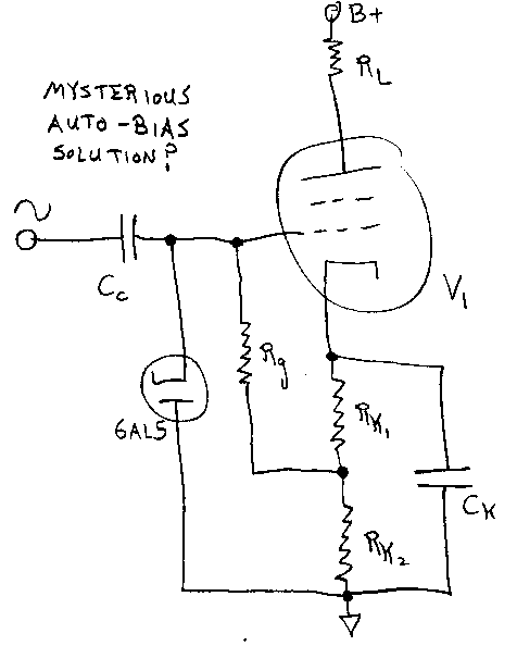
...The DC restorer clamps the bottom half of the grid drive signal, thereby imparting a DC value to the grid and simultaneously providing a mirror image of the plate signal. The result is that both plate and grid have corresponding DC values. ...
The circuit above doesn't clamp the bottom half of the grid drive signal. Bob also said the DC restorer doesn't have a time constant. The self-bias with bypass cap above seems to have a time constant.
"For lowest distortion, the drive signal on its grid should be a mirror image of the transformer drive signal and possess a corresponding DC value. It should be an identical haversine, differing only by the gain of the tube..."
The plate voltage signal is a whole sine wave. The plate current is a half-sine. I'm not following why the grid "should possess" a DC value corresponding to the DC value of the plate current. I think I'm still missing something.
Michael
"For lowest distortion, the drive signal on its grid should be a mirror image of the transformer drive signal and possess a corresponding DC value. It should be an identical haversine, differing only by the gain of the tube..."
Yes, in case of an ideal tube. But an art of amp design would not exist then.

As I wrote in my previous message, "ePay is the place where sailors of yestyears tell their fair tales".
Good reading though for a PFC.

Adamantium? what the hell is this? pure ** im sure. Plus that tranny is small but made to look big by the daft cover/bit of bent tin, mind you I dont dought Bobs design expertise and the transformer may be small for a reason. 220W RMS from four KT88? well it must be tetrode class ab with crazy anode voltage and fixed screen grid. Not exactly HI-FI but then what is?
It loks nice though, the parts are cheap but boutique parts are for audiofools and a good quality GP part is 99% as good as any expensive part. So maybe this is real?
Cheers Matt.
It loks nice though, the parts are cheap but boutique parts are for audiofools and a good quality GP part is 99% as good as any expensive part. So maybe this is real?
Cheers Matt.
Last edited:
Hmm looks like 6 (six) KT88s actually. Something accounts for the 42 lbs weight.. not the aluminum chassis. 16 lb PT, 16 lb OPT; The one pic shows the can about 70% full of iron with about a 5" thick lam stack. I find it credible (though at 200W I would be in the 20+ lb PT and OPT range I guess). Sure it's not class A triode...
Last edited:
There was an article with an amp design and schematic published in Glass Audio or Audio Xpress a few years back extoling a new discovery that allowed more power at lower bias currents in a Class AB P-P tube amp. I remember dismissing the idea due to some diodes being added to the output tubes grid circuit. I will see if I can find it, but the odds aren't great.
lol @ adamantium!!!! What next, Bananaramium?
Unobtarium. 1 billion Ramaohm per sq feet.
Reminds me of a warning sign in one of the EE labs at Clemson. It was the classic white background with black lettering and red lightning bolts...
"WARNING 10,000,000 OHMS!!"
It reminds me some rumor...
Back in USSR, when a new then Minister of Electronic Industry, Mr. Shokin, visited one semiconductor plant, he spotted a huge red banner with golden letters hanging above: "Praise Soviet Transistors, The Biggest Transistors in The World!"
However, he demanded to remove immediately that sarcastic humorous banner that all government leaders and politicians who visited the plant before saw, but nobody could understand what it really means...
"As far as component quality, maybe over the years Bob found out that there isn't any compelling reason to spend more than $0.20 on a resistor or $1.00 on a binding post ;-)"
I can tell you from directly talking with Bob Carver over several days that this is truly his take on electronics. He is an engineer, first & foremost, with TONS of vision & out-of-the-box thinking that have made him one h@ll of an inventor.
I see a lot of armchair EEs making disparaging remarks here, but as already a couple of members here have told you, we heard these amps first hand & they are the REAL DEAL. You can't touch anything remotely like them for twice the price.
I can tell you Bob is one SMART COOKIE, and you can crap all over his ideas, marketing strategy, etc., -- he won't care because he's just doing this for fun. He LIVES to experiment & solve age-old problems with new thinking. The day he quits inventing new stuff will be the day he dies....
& it's not like he NEEDS the money~
*rant over*
I agree with TNRabbit I have also talked with Mr. Carver as well as Rita, I have owned and repaired allot of Carver amps, are they the best? probable not, are they good for there original price point? hell yes. Bob Carver has introduced many creative and solid designs. Yes some of his inventions are shrouded in smoke and mirrors, but what manufacturer does not embellish descriptions to sell product??
There was an article with an amp design and schematic published in Glass Audio or Audio Xpress a few years back extoling a new discovery that allowed more power at lower bias currents in a Class AB P-P tube amp. I remember dismissing the idea due to some diodes being added to the output tubes grid circuit. I will see if I can find it, but the odds aren't great.
I think it used a quad of 6DZ7s and had zeners on the grids. Construction looked pretty messy.
- Status
- This old topic is closed. If you want to reopen this topic, contact a moderator using the "Report Post" button.
- Home
- Amplifiers
- Tubes / Valves
- Bob Carver's eye candy on eBay