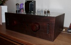
Well, in addition to the neohm 50R resistors in the I/V positions, I upgraded about 12 other resistors with a nice quality resistor. I also replaced the coupling caps with Duelund Cu PIO 1 uF coupling caps, which on purchased on sale from Parts Connexion.
I am very pleased with the end result.
I am very pleased with the end result.
Attachments
I bought a pcb from Broskie does anyone know what R18,R19 and C19 is for?
If they should be used?
What cap and resistors did you use at these slots, Ryssen?
If anyone is still experimenting with the Unbalancer circuit, I thought I'd post a link to this thread as Ian/Ruffrecords has found a circuit error on the original Unbalancer PCB (the PCB which has the PSU included).
http://www.diyaudio.com/forums/tubes-valves/253273-grid-resistors-gnd-3.html#post3878912
http://www.diyaudio.com/forums/tubes-valves/253273-grid-resistors-gnd-3.html#post3878912
Hello everybody, i'm really excited reading this thread, i can't stand in my shoes waiting to build my B III + Unbalancer DAC!
But i'm 1/2 steps behind you and stuck deeply in finding out how to assemble an Unbalancer even starting from Glass-ware PCB...
Could someone please suggest me all R and C values for an I/V stage Unbalancer for a B IIIse DAC?
I would use JJ ECC802 input and EH 6CG7 output tubes and 2.2/3uF C3 (too much?); a Janus Shunt Regulator to power B+ and Heaters, set to 250/260V and 12.6V.
Just to state one of my problems, i can't figure out R12 correct value to achieve this as i'm not able to quantify the current flow on it. How can i calulate current flow in the Unbalancer?
Thanks to anybody will be so kind to help me!
Just another question: i see 6n2p tubes need a different circuit layout from 12ax7, as they have filaments on pin 4 and 5 (and 6,3V power).
Could i mount them on Unbalancer as it is or should i implement some kind of adapting mod?
adapter 12ax7 ECC83 6N2 6N2P TUBES | eBay
Are you sure that it is needed? Reading the Unbalancer manual i see that 6.3V tubes heaters receive power from pins 4 and 5 (if you use a 6.3V power supply), so it should work anyway...
Am i wrong?
Too bad we can't ask Galss-Ware Audio directly: they never answer any mail...
6N2P pin layout seems just the same as 6N1P one to me. So, if 6N1P can be used without mod, why 6N2P can't?
12AX7 pinout is different when used in 12V circuit, but i read they can receive power at pins 4 and 5 too, when used at 6.3V. Is this untrue?
Thank you, but i'm still a little bit confused about resistors value. I'll find out about R12 values, but i'm not sure about i/v, cathode, anode and CCS resistors for the following tubes i have, to make Unbalancer work well:
- 12BH7
- 6N23P
- 6N2P
I would like to try 30 ohm i/v resistors for the latter, but Broskie's schematic here The Unbalancer shows 34R CCS resistor using 60R i/v resistors: he fears that using 30R i/v resistors, cathode voltage would be too low for CCS to work OK (6N2P has a very low anode current of about 2mA), so what resistors should i use for CCS set and cathode resistors with 30R i/v resistors? 120K for anode is OK?
50 ohm i/v should be OK for 12BH7 and 6N23P, i guess i should use 6.8R CCS and 300R cathode resistors, am i wrong? Then for anode i should stay around 24K for both? Could i lower i/v resistors any more (mostly using 6N23P)?
I will use Unbalancer as a preamp in my system so i would need 2V output at least...
Last edited:
- Status
- This old topic is closed. If you want to reopen this topic, contact a moderator using the "Report Post" button.
- Home
- Source & Line
- Digital Line Level
- BIII with Broskie Unbalancer vs. EE Minimax Plus - My experience