Member
Joined 2009
Paid Member
That is why working on unclad board, I put the output transistors and bias sense part on a separate heat sink. with 10 cm long wires running to the input board so I can experiment with both sides at will. BTW my project uses TO3 transistors left over from a failed experiment (dynaco ST120). So far I've killed any oscillation with a 33 pf cap b-c on the input transistor, in addition to the 150 pf b-c cap on the VAS from the old design.I haven't had much experience of working with perf board but I guess one of the main things is to lay out the parts so that it isn't too difficult to install them and replace them whilst you are experimenting. If you want to experiment it would be really convenient if you can access both sides of the board whilst the power devices are bolted to a heatsink and powered up. This way you can probe voltages anywhere on the circuit easily. And you can replace parts without taking the power devices off the heatsink. If you want to have this flexibility, put the power devices on one edge of the board, standing up, so the board can be perpendicular to the heatsink.
thanks for doing experiments on an output capacitor amp with complementary output transistors, something the other designs (Apex6, Ellis Basic 50, maouna, Sakis G amp, Motorola 5W, Armstrong 621, Leak ST70) haven't done.
If I wasn't deep into modifying the pwg-tang mod of the ST120 board (which doesn't bias properly) I'd build one of these on nema C board. (But I don't have MJ15004, the complement to the NTE60 OT's I have left over) Pwg-tang clamped his two diode and a pot stack bias control, sub for VR2 R12 and Q3 on TGM8, with a red LED. That doesn't work, one solder error and the LED becomes a 40 ohm resistor. I clamped the pot only with a 1n4148 diode, which won't work with the transistor setup you have.
Last edited:
Can you post the pdf pcb for this two side board?Yeah sure did. My contact there gave me advance notice of the cutoff date, so I worked to that. Unfortunately, I wasn't able to get my quasi project boards finished in time :-(
Member
Joined 2009
Paid Member
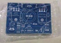
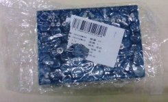
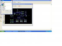
Hey guys, some "teaser" shots the board house sent me before putting them in the mail.
 you've done a nice job, looks like a promising board.
Can you post the pdf pcb for this two side board?
I've never tried to output a PDF from Eagle, but will try and work it out tonight.
The proof is (a) whether it works and (b) whether it sounds any good. I'll let you know

Ok. here is the way,if it usefulI've never tried to output a PDF from Eagle, but will try and work it out tonight.
The proof is (a) whether it works and (b) whether it sounds any good. I'll let you know
Attachments
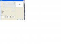
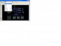
No,you must press,view,display,hind layers,bottom,pads,vias(checked) and print this first.Hi timinos, is this what you want?
Then press,view,display,hind layers,top,pads,vias (checked)and print again.
Press view,display hind layers,press none,mark bottom-pads-vias press ok.Now you see bottom traces and pads only!That is what you must print.
Because you have a dual layer board you must print the onother time.
Press view,display hind layers,press none,mark top-pads-vias press ok.Now you see the top traces only!That is what you must print.
Finaly you have two different pdf,one show the top and the other the bottom traces(nothing else,only traces in black&white).
Hope this help.
Attachments
Last edited:
Member
Joined 2009
Paid Member
Andrew, I asked myself the same question about posting layout files but in the end I decided to do so. So long as Christian is OK with it I'd say "so what if they do" make copies - then perhaps more people will enjoy the amplifier. I suspect there's very little profit to be made selling small boards if you take into account your own labour effort.
Last edited:
I agree with that Gareth. This is just a hobby for me so I'm not interested in profiting from my it. I seriously doubt there is any money to be made from this type of stuff, but if the Chinese rip off my PC board and make a few bucks then so be it
I'll post up the Eagle files once I've built and tested.
I'll post up the Eagle files once I've built and tested.
Member
Joined 2009
Paid Member
- Status
- This old topic is closed. If you want to reopen this topic, contact a moderator using the "Report Post" button.
- Home
- Amplifiers
- Solid State
- Bigun's TGM8 with Single Supply