The early prototypes – Phase Control 
For phase control of the oscillator feed to the 6146W, one could
mount a laser transceiver (infrared spectrum) on one side of a, say
12' PVC tube, and then mount a mirror on a freely moving / adjustable
(magnetically from the outside) cylinder located inside the tube.
10MHz waves are about 100' long. 5 laser transceivers coupled in
series x 12' x 2 = 120 foot range, giving more than 360 degrees of control.
I hope the above doesn't sound too Rube Goldbergian
This together with a 'phase locked' and variable duty cycle square wave
from the oscillator could optimize the operation of the 6146 based tesla coil.
Resonator phase control with 1 degree resolution (for a tesla coil based power supply
Here is a suggestion for a phase control module giving 1 degree resolution,
also with a lesser "RG–factor" d:
When the resonator operates at 10MHz, one degree is 3.27857018819 inches long.
I believe the most interesting area is very close to 'phase sync', some 25 degrees
ahead and 5 degrees behind this point for adjustment should be OK.
Then an air coil wound with magnet wire at a length of 3.28" x (360 - 25) = 1098 inches
makes for the start point, giving a delay near one wavelength.
The next 5 coils to be patched in series with this first have the following values:
Coil #2 3.28"
#3 6.56"
#4 13.11"
#5 26.23"
#6 52.46"
Adding these in a binary fashion gives a 1 degree resolution. Adding a 7th coil and halving
each coil's (except the first) overall length would give a 0.5 degree resolution.
Swing seat
Let us imagine ourselves the resonating wave in a tesla coil eventually represented as a kid sitting in a
swing seat tied to the low branch of a tree.
Then imagine someone pushing the kid into motion.
Pushing with the right timing, very little force is needed to set the kid/the wave into and maintain the swinging motion.
And on the other hand, a lot of force can be wasteful – even stop the motion all together.
Positive input to the coil should largely be on the positive stroke, that is from the wave is at its top, the nearest point and outwards.
One good way to get more voltage in this particular application (a tesla coil based PSU) is by an accurately timed square wave input.
I am looking for a good power supply unit to source the 'full range atmospheric high voltage field transducer'. I think this one is promising, and not much complicated – very few parts are added, and except maybe for the MAX038 (in some countries...) they are also rather affordable.
bigwill said:Don't make it too complicated, keep it simple and it has more chance of working
Nixie said:Yeah, I second that.
Let us imagine ourselves the resonating wave in a tesla coil eventually represented as a kid sitting in a
swing seat tied to the low branch of a tree.
Then imagine someone pushing the kid into motion.
Pushing with the right timing, very little force is needed to set the kid/the wave into and maintain the swinging motion.
And on the other hand, a lot of force can be wasteful – even stop the motion all together.
Positive input to the coil should largely be on the positive stroke, that is from the wave is at its top, the nearest point and outwards.
One good way to get more voltage in this particular application (a tesla coil based PSU) is by an accurately timed square wave input.
I am looking for a good power supply unit to source the 'full range atmospheric high voltage field transducer'. I think this one is promising, and not much complicated – very few parts are added, and except maybe for the MAX038 (in some countries...) they are also rather affordable.
Breaking News
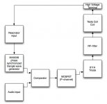
The 6146W pentode stage has been replaced by a power triode stage.
Previously there were two signal inputs to the 6146 pentode; one finely synced however otherwise
"dumb" square wave from the oscillator, and one audio modulated drive voltage.
Since the MAX038 also generates a pretty decent triangle wave; why not use this for creating a
real audio modulated PWM drive from the oscillator directly?! running at 10MHz!
One other feature is that with the PWM module one has the choice of operating in negative
and positive amplitude modes (simply by switching polarities in the comparator).

Lifter vehicle + modified plasma tweeter driver
... it looks like I did my usual mistake, confusing amplitude and/with phase inversion
Anyhow, this feature isn't really needed here
me said:
One other feature is that with the PWM module one has the choice of operating in negative
and positive amplitude modes (simply by switching polarities in the comparator).
... it looks like I did my usual mistake, confusing amplitude and/with phase inversion
Anyhow, this feature isn't really needed here
PWM module
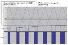
The grid of the 811A is now driven by an 'embedded audio signal'.
This pulse width modulated square wave can have a maximum duty cycle of
50% or half the oscillator wave length. To achieve this, the triangle wave from
the MAX038 has to be double the amplitude of the peak maximum audio signal.
And then the audio signal is lowered/biased so it doesn't go beyond the zero point
level of the triangle wave.
On the other hand, there should also be some PWM output even when there is
no audio signal present, so as to keep the oscillator going.
I'll make a more detailed schematic some day soon.
Hmm, reading the high voltage transistor thread:
This guy has beat us to it! Maybe this is a clue that the concept does work... (or maybe he was hearing the vibration of the heatsinks being attracted to ground with the audio signal, or something, I don't know  )
)
maudio said:For the brave-at-heart:
found a schematic of one of the bigger ones I built, do not try this at home
This guy has beat us to it!
Maybe this is a clue that the concept does work... (or maybe he was hearing the vibration of the heatsinks being attracted to ground with the audio signal, or something, I don't know )42bit 96kfps Holographic Sound Project
The more, the merrier d:
and we have just barely started, more to come
bigwill said:Hmm, reading the high voltage transistor thread:
This guy has beat us to it!
The more, the merrier d:
and we have just barely started, more to come
Lifter vehicle + modified plasma tweeter driver
Eh, thanks for that, we're in this all together right
... modulated trough a tesla coil 'transformer' where the coil with valve–stage functions as both primary and secondary, rectify? (too early in the morning to see this clearly...), yes that should probably work. 20 kV = lots of amplitude
bigwill said:Hmm, our findings (well mostly yours
Just use modulated high voltage/ frequency through a transformer and rectifiy and smooth it on the secondary to get audio..
Eh, thanks for that, we're in this all together right
... modulated trough a tesla coil 'transformer' where the coil with valve–stage functions as both primary and secondary, rectify? (too early in the morning to see this clearly...), yes that should probably work. 20 kV = lots of amplitude
Coil self resonance test circuit, etc.
The modification of the plasma tweeter driver may take a while longer.
A partial output from a search for 'self resonance'; http://www.imagineeringezine.com/PDF-FILES/coiltest.pdf
Instead of right away starting a build around the 811A triode I plan to work a little with waveforms in a full scale coil, fed comparably low voltages (somewhere <30 Volts), incorporating the PLL, delay and PWM circuits. And then study waves for a while
A link with relevance to the coil resonance frequency, 'Wire length quarterwave'; http://www.abelian.demon.co.uk/tssp/misc.html
MOSFET–stage transducer driver
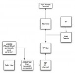
Since the coil resonance is constant and non–drifting, the modified tesla coil based Biefeld–Brown effect based driver could be driven directly by a MAX038 that is tuned to the resonance frequency of the coil. That is, without any external 'clock input' from the coil. This way there are probably no need for the phase sync and phase adjustment/delay circuitry.
My previous calculations for the phase adjustment where no good anyway
Attachments
Solid State plasma tweeter driver
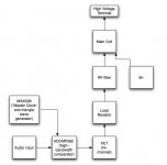
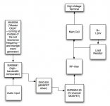
Simulating a resonator circuit I got some indication that a master clock running at
multiples or 'early harmonics' of the resonance frequency gives comparably higher
voltages (lowering the coil resonance = extended wire length, giving more amps).
The comparator has been replaced with one that is a bit easier to work with.
edit: I have a feeling that I may in this some day wake up to the ever returning
amplitude invertion problem, so some lobbying towards the Audacity programmers
might be a good thing
Attachments
- Status
- This old topic is closed. If you want to reopen this topic, contact a moderator using the "Report Post" button.
- Home
- Loudspeakers
- Planars & Exotics
- 'Biefeld-Brown effect' based full range drivers