The 038 is such a versatile chip d:
From its data sheet
<<Duty Cycle
The voltage on DADJ controls the waveform duty cycle (defined as the percentage of time that the output waveform is positive). Normally, VDADJ= 0V, and the duty cycle is 50% (Figure 2). Varying this voltage from +2.3V to -2.3V causes the output duty cycle to vary from 15% to 85%, about -15% per volt.>>
If a 2 Volts peak–to–peak audio signal was fed to the DADJ pin of the 038 the result would be an amplitude inverted PWM output (with the chip set in 'square wave mode') that can drive a MOSFET directly. This is very convenient, at least for an early prototype.
At 2.3 Volts the pulse width is 15%
1.3 V = 30%
0.3 V = 45%
0 V = 49.5 % (maximum pulse width in this application is 50% of the coil's oscillation frequency)
This way the coil always has a signal feed, so no need to start it up at first. When there is no audio signal present the coil is fed the maximum duty cycle signal (the amplitude inversion feature, needed to make a positive output from a positive input).
(The problem now is, an amplitude inversion is here not needed.... the never ending story .... so an amplitude inverter is here needed! I have some low voltage pencil size tubes that might serve this purpose, as a preamp hack).
The plan is to start a build with a coil fed some 30 Volts at first.
To avoid frying the 038 at an eventual MOSFET failure, one could use a wireless headphone set for a safe link between the 038 and the FET, but then some FET driver stage would need to be added after all.
Without the wireless stage the parts list isn't very long;
mainly
1 MAX038
1 BUZ 100
1 main coil
add a few more discrete components, including RF–filter(s)
and a 30 V PSU
Solid–state plasma tweeter driver
The signal here is at about 10MHz so this wireless headset would require a major hack
An alternative would be to install a fat zener diode between the gate of the MOSFET and ground.
me said:
To avoid frying the 038 at an eventual MOSFET failure, one could use a wireless headphone set for a safe link between the 038 and the FET, but then some FET driver stage would need to be added after all.
The signal here is at about 10MHz so this wireless headset would require a major hack
An alternative would be to install a fat zener diode between the gate of the MOSFET and ground.
Reading data sheets....
After reading the data sheets more close, the 038 can not possibly drive a BUZ 100
or similar directly.
And a <<Change in Output Frequency
with DADJ Fo/VDADJ ±2.5 – ±8 %>>
This isn't very acceptable. So it looks like I am going with Plan A instead. Plan B is good
for testing voltages though (without the audio input).
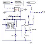
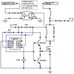
Optical Link
Here is a schematic for an optical link and MOSFET driver, based on
the schematic from http://www.electronics-lab.com/projects/misc/017/index.html
Here is a schematic for an optical link and MOSFET driver, based on
the schematic from http://www.electronics-lab.com/projects/misc/017/index.html
Attachments
Hardware Engineers
It seems that this project could need hire a few good hardware engineers...
The phototransistor had a faulty/reversed polarity in the schematic posted previously.
And the circuit's bandwidth is probably not high enough for a 10MHz signal (I couldn't
get the 555 started in the simulator to verify).
The main reason for the optical link is to avoid frying the master clock at an eventual
fault in the MOSFET, for simplicity it could well be omitted.
This thread looks more like a blog than a discussion for now
Hopefully there will be some apparent progress soon, hardware, pictures, sound d:
Attachments
Lifter vehicle + modified plasma tweeter driver
Good to know we are more people here
About the recent schematics, I hope no one tries to build anything based on them directly,
For they are very incomplete, and should at this time best be considered 'abstract ideas'.
Using a MOSFET for driving the coil. There are some advantages over those using
a triode, simplicity for one. However if a MOSFET is fed a dirty signal, or one exceeds
its various ratings and it then fails, the result is that the path between Source and
Drain is being 'welded' so that it stays on permanently, passing the source/B+ voltage everywhere.
In other words, the complete opposite to the behavior of a fuse (who at 'failure' would be
breaking the circuit).
My DIY optocoupler is somewhat far fetched – although if it worked the isolation would be
very good. To make it work (at a wide bandwidth) its operation should be based on modulation
rather than switching = more complicated.
The HCPL-3120 optocoupler and MOSFET driver has a switching speed of 500ns. The
length of one 10MHz wave is 100ns, so using this chip the coil frequency would have to
be lowered (Many multiplexed optocouplers could be another way... even more complicated).
(For sure, there are faster single channel optocouplers around)
A useful PWM signal moving through this optocoupler could have a wavelength of 3us,
allowing for a resonance frequency of 300kHz, making the coil somewhat bulky.
For early prototyping, one could instead use the XR2206 frequency generator as the master
clock, skip the optocoupler and connect it directly to the MOSFET driver. The coil resonance
frequency could be set to 1MHz (less bulky coil) and at a failure the cost would be some 1/4
of that of an 038, or less.
Feeding the coil 18 Volts one might even avoid a breakdown of the 2206 altogether. Running
at 1MHz, 50% duty cycle and 18 Volts I would hope for an output at the High–voltage Terminal
of some 300 Volts. Scaling the B+ from 18 up to 1200 Volts should then eventually give 20 kV
or more.
bigwill said:Don't worry I havn't forgotten about this thread
Good to know we are more people here
About the recent schematics, I hope no one tries to build anything based on them directly,
For they are very incomplete, and should at this time best be considered 'abstract ideas'.
Using a MOSFET for driving the coil. There are some advantages over those using
a triode, simplicity for one. However if a MOSFET is fed a dirty signal, or one exceeds
its various ratings and it then fails, the result is that the path between Source and
Drain is being 'welded' so that it stays on permanently, passing the source/B+ voltage everywhere.
In other words, the complete opposite to the behavior of a fuse (who at 'failure' would be
breaking the circuit).
My DIY optocoupler is somewhat far fetched – although if it worked the isolation would be
very good. To make it work (at a wide bandwidth) its operation should be based on modulation
rather than switching = more complicated.
The HCPL-3120 optocoupler and MOSFET driver has a switching speed of 500ns. The
length of one 10MHz wave is 100ns, so using this chip the coil frequency would have to
be lowered (Many multiplexed optocouplers could be another way... even more complicated).
(For sure, there are faster single channel optocouplers around)
A useful PWM signal moving through this optocoupler could have a wavelength of 3us,
allowing for a resonance frequency of 300kHz, making the coil somewhat bulky.
For early prototyping, one could instead use the XR2206 frequency generator as the master
clock, skip the optocoupler and connect it directly to the MOSFET driver. The coil resonance
frequency could be set to 1MHz (less bulky coil) and at a failure the cost would be some 1/4
of that of an 038, or less.
Feeding the coil 18 Volts one might even avoid a breakdown of the 2206 altogether. Running
at 1MHz, 50% duty cycle and 18 Volts I would hope for an output at the High–voltage Terminal
of some 300 Volts. Scaling the B+ from 18 up to 1200 Volts should then eventually give 20 kV
or more.
The eventual MOSFET failures
I wrote <<...if a MOSFET is fed a dirty signal, or one exceeds its various ratings
and it then fails, the result is that the path between Source and Drain is being
'welded' so that it stays on permanently, passing the source voltage everywhere.>>
This should be; when a N–channel/NPN MOSFET fails, in the short microsecond
before its drain and source are being welded together, the drain voltage flows
everywhere, including through the gate section and everything connected to it.
Lifter vehicle + modified plasma tweeter driver
Here is a promising 'all glass' triode design.
http://www.triodeel.com/simple45.gif
One could replace the 2A3 with a 811 (4A needed for the heater), replace
the output transformer with a 'quarter wave coil', couple the B+ via a load
resistor to the base of the coil and inject the PWM signal at the audio input.
(The .33uF/630V capacitor can possibly be omitted)
Lifter vehicle + modified plasma tweeter driver
.... I read somewhere that the 811 needs some 5 Watts on the
grid to operate at its fullest. IOW, lots of room for an upgrade,
also concerning the load/B+ voltage.
On the other hand, why mess with the 2A3 – this triode would
do just fine, as the rest of the design (except possibly for the
coupling capacitor).
Lifter vehicle + modified plasma tweeter driver
Good to hear
And this is now partially a class D project (again) since the input to the power amp section
is all PWM.
Did we
I wonder what your thoughts are on the lifter vehicle section
classd4sure said:Hey,
I haven't forgotten about this thread either. I admitt I have some catching up to do with it though.
Good to hear
And this is now partially a class D project (again) since the input to the power amp section
is all PWM.
Nixie said:I think they lost me a few pages back...
Did we
I wonder what your thoughts are on the lifter vehicle section
The way I see it, and I'm low on sleep so I may be way off, is: Depending how you reference it to ground, you're going to have at the very least half the total combined output voltage difference between the secondary and primary on one of the transformers. Think of the primaries in parallel as one shared primary, and it's easier to see this. All the primaries have the same potential, whereas each secondary is one potential away from the other ones, so at most one secondary can be within the insulation's rated voltage. If this secondary is centre-tap-referenced to ground, it's two neighbors will be 1x secondary voltage each away from that potential, and the two endpoint transformers, 2x away. If one of the endpoint secondaries is referenced, even worse, as the other endpoint one will be 4x above that and will most likely fry though the insulation to the primary, as I doubt any transformer would have that much overrated insulation. Doesn't matter if there's no actual reference to ground; if the windings are floating, just think of it as some random reference.
- Status
- This old topic is closed. If you want to reopen this topic, contact a moderator using the "Report Post" button.
- Home
- Loudspeakers
- Planars & Exotics
- 'Biefeld-Brown effect' based full range drivers