N-channel mosfets aren’t necessarily any better for SOA than MJ15024’s. Especially new types. If you’re going to do this, use an older type which has been around since the dawn of time, and *isnt* optimized for low Qg and fast switching. The older types actually had decent DC SOA.
FDA 69N25 2 pair in Class AB should working good without faults +/-70 V Rail
Ecler did use 2 decades ago IRFP360
Here you go")
nice pictures.. thank's
with what did you clean your facade so well not to erase the inscriptions, because mine is a little scratched and black has faded over the years. for the cover of the transistors I will be able to repaint it in black because no problem.
I put a PC fan which consumes 80ma, do you think that I can take the power supply on the 15VDC with a resistive bridge or a regulator without this risking anything? because there is no real information on the characteristics of the outputs of the power supply transformer on the secondary ?
the only thing I see is that it is written 1.5A for 240VAC on the fuse placed on the plate of the supply capacitors. this is the only info I have.
Phil
I used something called a "Magic Eraser" to clean the faceplate, Im not sure if that product is available outside of Canada or not.
Explore Magic Erasers Cleaning Products | Mr Clean(R)
I cleaned the two potentiometers while I was in there. Due to there orientation, the removal of the faceplate was needed to have good access to the undersides of the pots. Removing the faceplate is no fun at all let me tell you. I would be happy to outline the procedure should you wish to do that.
I also removed the Lexan cover over the meter assembly and cleaned both sides with a car polish.
Take a look at the link below, it is of a rebuild of a 750B a few years back. There are a lot of good pictures and information there.
Look what followed me home | Phoenix Audio Community Forums
Judging by the size of the wire alone, I would imagine that the 1.5 amp fused 12vac secondary winding is capable of far more than what the fuse is rated at.
Besides powering the protection circuit board, it provides power for the power-on LED indicator for the BGW "C" models using the same brown terminals found on the clip indicators. You may be able to use that to power the DC fan.
@Michael F
thanks for the links .
I also completely disassembled the front to clean it well and access the plastic of the sight meters and I also cleaned and relubricated the potentiometers, not an easy job.
to be sure, i'm going to ask DUKE if he has any info on it, but i'm going to note the current intensity before
Phil
hi Duke,
when you speak of +/- 300mv precisely?
is it +/- 300mv in the positive of the voltage or +/- 300 mv in the negative of the voltage.
because on the right channel I have -265mv and precisely on the left channel which was defective I have + 460mv from there comes my question.
Phil
when you speak of +/- 300mv precisely?
is it +/- 300mv in the positive of the voltage or +/- 300 mv in the negative of the voltage.
because on the right channel I have -265mv and precisely on the left channel which was defective I have + 460mv from there comes my question.
Phil
hi Duc,
thank you for this information, I am not a basic electronic technician but only an electromechanical engineer in the industry.
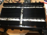
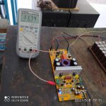
what I also noticed is that on the screws that hold the 5 transistors MJ540 + Mj 550 + MJ720, I have the power rail which also comes on the heatsink? as I have isolated by two boards the amplifiers of the box for the moment this does not stop any problem, but I also have a big doubt of having a leak, I experienced this with the C1 tantalum which leaked towards the HP output . for the moment I feed the amplifier via a variable transformer at 80Vac and
I have a lot of difference in the balancing of the lm318 power supply: for example positive side 6vdc and negative side -3.06 vdc, it is not balanced, I have a small difference on the Right channel but not in time.
I will still look for tomorrow. at this power level of 80VAC, I have +/- 30VDC and the amplifier gives a good sound, but not yet well repaired
Phil
thank you for this information, I am not a basic electronic technician but only an electromechanical engineer in the industry.
what I also noticed is that on the screws that hold the 5 transistors MJ540 + Mj 550 + MJ720, I have the power rail which also comes on the heatsink? as I have isolated by two boards the amplifiers of the box for the moment this does not stop any problem, but I also have a big doubt of having a leak, I experienced this with the C1 tantalum which leaked towards the HP output . for the moment I feed the amplifier via a variable transformer at 80Vac and
I have a lot of difference in the balancing of the lm318 power supply: for example positive side 6vdc and negative side -3.06 vdc, it is not balanced, I have a small difference on the Right channel but not in time.
I will still look for tomorrow. at this power level of 80VAC, I have +/- 30VDC and the amplifier gives a good sound, but not yet well repaired
Phil
Good morning all ,
I finally finished its repair and now it sounds like a god, it's been two days that it runs on my JBL E100 and it has a great sound rendering as I like.
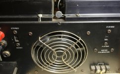
only small flaws that I still have to improve is the resonance noise of the transformer.
however I had placed a rubber sheet, but I forgot to place some in a place which still gives me a noise of 50hz when the amplifier itself is turned on, I have nothing in the High speakers.
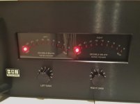
small detail to finish and I also noticed that an orange led was out of order, I had not changed those there during the modification by green leds on the first 5. then the IDLE mode led that I placed in blue is too bright, so I'm going to change its resistance to reduce its brightness and if that does not suit me then I replace it with a green led so that it remains homogeneous in the display.I arrive at the end of the tunnel.
I finally finished its repair and now it sounds like a god, it's been two days that it runs on my JBL E100 and it has a great sound rendering as I like.
only small flaws that I still have to improve is the resonance noise of the transformer.
however I had placed a rubber sheet, but I forgot to place some in a place which still gives me a noise of 50hz when the amplifier itself is turned on, I have nothing in the High speakers.
small detail to finish and I also noticed that an orange led was out of order, I had not changed those there during the modification by green leds on the first 5. then the IDLE mode led that I placed in blue is too bright, so I'm going to change its resistance to reduce its brightness and if that does not suit me then I replace it with a green led so that it remains homogeneous in the display.I arrive at the end of the tunnel.
Gratulation and enjoy
its a great amp design,
have using in my apartment 750B with Infinity kappa and Infinity studio monitor, ypu can feel bass eahrtquake in your bathroom
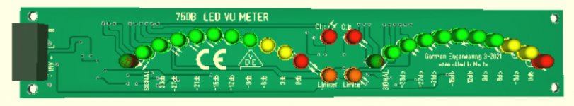
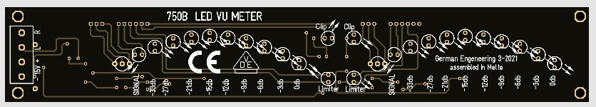
have rebuild during Covid-19 lockdown 750B VU Meter for Class D
its a great amp design,
have using in my apartment 750B with Infinity kappa and Infinity studio monitor, ypu can feel bass eahrtquake in your bathroom
have rebuild during Covid-19 lockdown 750B VU Meter for Class D
Attachments
Nice LED boards, are they available for purchase?Gratulation and enjoy
its a great amp design,
have using in my apartment 750B with Infinity kappa and Infinity studio monitor, ypu can feel bass eahrtquake in your bathroom
have rebuild during Covid-19 lockdown 750B VU Meter for Class D
Gratulation and enjoy
its a great amp design,
have using in my apartment 750B with Infinity kappa and Infinity studio monitor, ypu can feel bass eahrtquake in your bathroom
have rebuild during Covid-19 lockdown 750B VU Meter for Class D
hello Nmos,
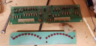
as always you realize great CI. is it the same format that can replace the original on the map without having to change anything or are there any connections or other things to do to place it in place of the original one, because the meter view map is in 2 rooms connected by pine trees.
Phil
Attachments
Differences in 750C Power Module Boards
Can't believe I am contributing to a 20 year old thread but here it goes. I recently picked up a couple of 750Cs. Other than the annoying power transformer mechanical noise, one works fine. One has a distorted channel. Looking at the board, I noticed several parts with broken leads that obviously need replacing. I also noticed that I have 3 versions of the circuit boards.
9007-0751B
9007-0751D
9007-0751E (2 of these in the amp that works).
I know there are really knowledge folks on the thread that can shed light on this.
1. Do they need to be the same series to work in strap mono mode.
2. Do the schematics that are in HIFI engine reflect the circuit in all three board versions?
3. What are the main differences between the 3 versions?
The 0751D has cut traces and tacked on resistors and caps. It has obviously been worked on. I am having doubts that this board will work even after parts replacement.
All the power transistors checked out...
hello Nmos,
as always you realize great CI. is it the same format that can replace the original on the map without having to change anything or are there any connections or other things to do to place it in place of the original one, because the meter view map is in 2 rooms connected by pine trees.
Phil
Its Original LED 750B circuit and it will work with all BGW 750 amplifiers, but PCB Board is not plug and play, connectors and size are different.
Original LED 750B is designed to add for DISCRET Class D 1000W 4 Ohm
Attachments
Can't believe I am contributing to a 20 year old thread but here it goes. I recently picked up a couple of 750Cs. Other than the annoying power transformer mechanical noise, one works fine. One has a distorted channel. Looking at the board, I noticed several parts with broken leads that obviously need replacing. I also noticed that I have 3 versions of the circuit boards.
9007-0751B
9007-0751D
9007-0751E (2 of these in the amp that works).
I know there are really knowledge folks on the thread that can shed light on this.
1. Do they need to be the same series to work in strap mono mode.
2. Do the schematics that are in HIFI engine reflect the circuit in all three board versions?
3. What are the main differences between the 3 versions?
The 0751D has cut traces and tacked on resistors and caps. It has obviously been worked on. I am having doubts that this board will work even after parts replacement.
All the power transistors checked out...
its simple and reliable circuit, but with todays transistor capacitor value need update
you need to check for oscillation
old transistor throw it away
Hi kwingylee,
NMOS is right, often transistors have been replaced and are not matched to the rest. Today's transistors are far superior if you are going to listen to it. I still work on them.
Get the manual, the parts changes are in there and you may find them to be fine. I would use MJ2119x transistors. Pay very close attention to the setup procedure. If you actually follow the manual, your amplifier will perform well. You really do need to use an oscilloscope and good DVM in order to work on any amplifier. You absolutely must check for oscillation, and don't even dream about replacing the LM318 op amp with something else. You need more equipment and experience to compensate the amplifier with a different op amp. The gains are small anyway. The slew rate of the LM318 is 50 V/uS, and in feed forward can reach 70 V/uS. It is a fast stinker, so don't mess with it.
-Chris
its simple and reliable circuit, but with todays transistor capacitor value need update
you need to check for oscillation
old transistor throw it away
If the outputs are mismatched, you don’t want to use them in the amp that’s for sure. You may in any case want to upgrade to ON 21194 for improved sound quality. But if you have ANY of the original RCA outputs you don’t ever want to *throw them away*. Either keep them in your stash or give/sell them to someone who can use them. Many older amps use these types and won’t need a complete set of 20 (the 4 drivers are different).
- Home
- Amplifiers
- Solid State
- BGW 750B output modules