
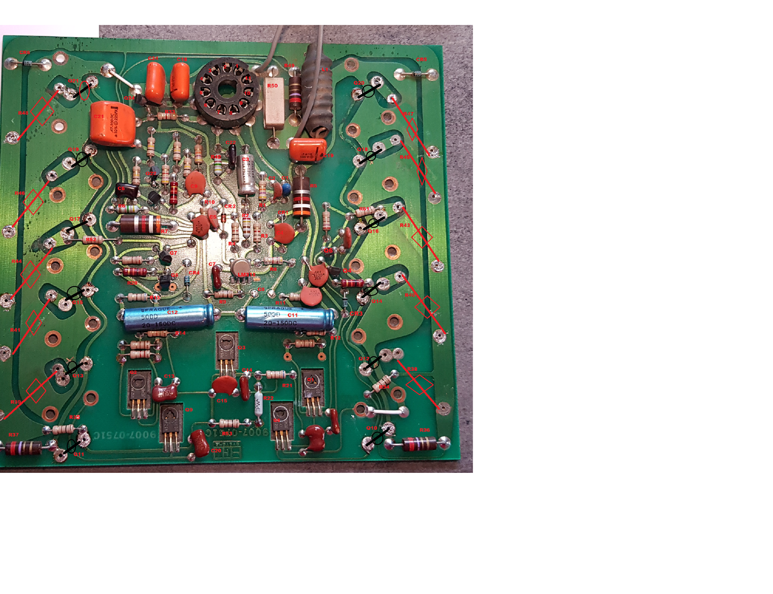
Here are the broken components (pastes or completely cracked in Red color.
3 chemical capacitors to replace given their ages in yellow color
I saw that we were talking about placing in parallel above other non-polarized capacitors but I do not know their values and for what precise use.
I am not an electronics engineer, I am an electromechanical maintenance engineer, so I do not understand everything about this electronics that you are improving.
Phil
Do you using the amp at home ? then Fan is very noisy
If you have electronic skills, you can upgrade to 12V PWM temperatur controlled FAN Speed / FAN off < 40 degress heatsink.
I did make this changes with my 750B, because its running at home to drive large HI-FI speaker and subwoofer.
hello,
How did you connect the PC fan, I have a Noctua Pc fan designed for 3 speeds with a consumption of 80ma. I was thinking of plugging it into the 15vdc socket of the vu meter (connector at the relay level) with a 12vdc zener to adapt the voltage.
Is this what you have achieved or have you placed an additional 12vdc power supply?
thank's Phil
I too replaced the fan in my BGW 750A with a brushless DC fan which runs very quiet. I added a separate power supply - careful with the orientation of the replacement fan.
Details in my restoration thread
BGW 750A - output transistors
Rgds
Mayank
Details in my restoration thread
BGW 750A - output transistors
Rgds
Mayank
hello,
Today I fed the right channel with the variable transformer up to 100v as a test and gently put the voltage back on the condos like that without forcing.
by looking more closely, see my photo below, the meters all have red leds? except on the photo below which comes from the WEB can we see green, orange and red leds? strange.
it's already a good start because he hasn't toured for 10 years,I did not feel any input signal or output load .
the right channel had the symmetrical tension on each side. I think it is in good condition but there will certainly be a difference with the left channel which will have MJ15024 / 25 instead of the original SJ7394 and SJ7407.
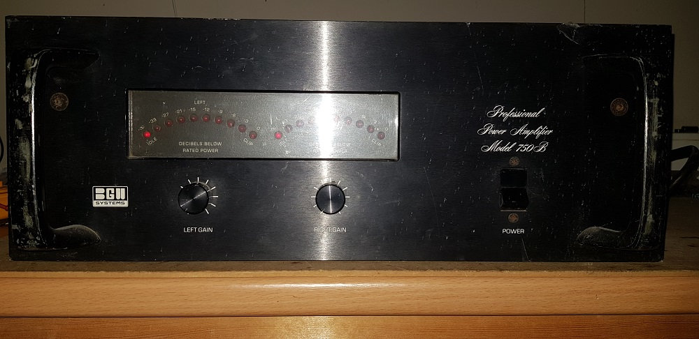
my facade with all the red leds
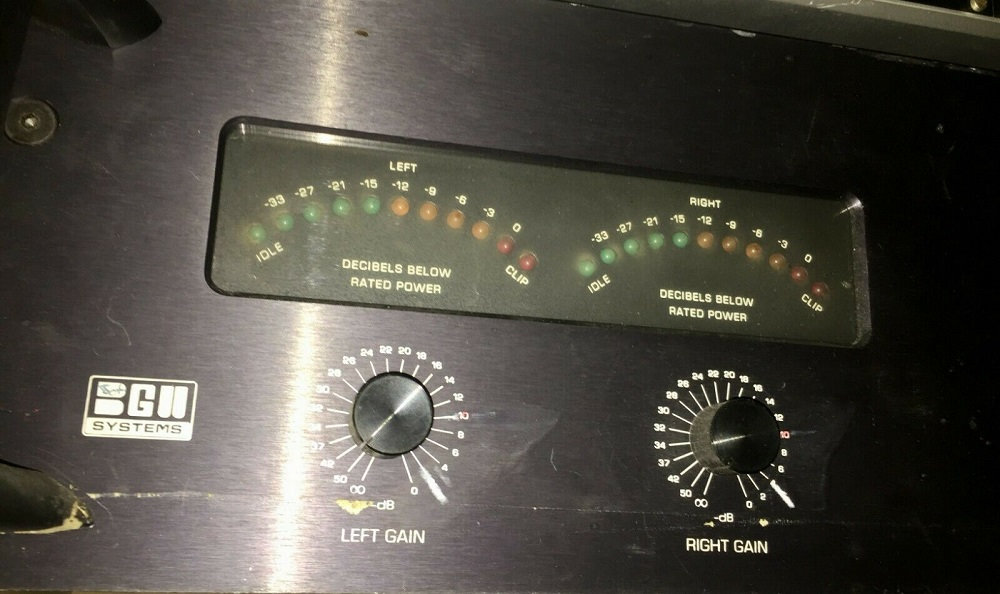
photo taken on the web.
for 15VDC on board speakers protection, i think's replace 2 condos 330uf by 2 condos 2000uf to hold the voltage to place a zener resistance of 12vdc and the 12vdc 40ma Noctua fan.
Phil
SJ7394 and SJ7407 are matched in House Parts
This output transistors are matched for same Beta
750B have no Basis resistors
Later BGW use MJ15024 and MJ15025
I dont know they are matched, you need to ask Duke / Audioman1
In German Night Club Dorian Gray @ Frankfurt Airport 1978 to 31.12.2000
many 750B was installed with Richard Long sound System
great sound
Hello,
I would like Duke to come through here, I sent him a PM but no response. there might be a photo of the component locations in these archivesi started listing
the numbers on the IC, but i think i have some errors. not easy when you are a beginner in this kind of device.
phil
I would like Duke to come through here, I sent him a PM but no response. there might be a photo of the component locations in these archivesi started listing
the numbers on the IC, but i think i have some errors. not easy when you are a beginner in this kind of device.

phil
Last edited:
We had same Problem in Club installation trough the heat,
transsistor have end of live.
Replace Transistors, LM318 and amp will working again years of trouble free
Habe a look: BGW 750 B redesign 80x180 same circuit with LM318
but with improvements
XLR Differential Input with Clip Limiter
Short Circuit protection,
Cascoded Second stage
Turn on Delay / OFF without Relay - no turn on/off thumps
topology comes from Class D UcD circuit
DC Protection (Triac Crowbar)
Switching Rails Class EEEngine prepared
Attachments


Hi All
I have seen lots of new work done on many old products. I don't know what I can offer other than help fill in some old history. I'm still active developing new products and service Audio precision System Ones, Two, Cascades and ATS2 and make the APIB USB ADAPTERS that them work on modern computers.
I have posted some additional data on old BGW products.
BGW AMPLIFIERS
OUTPUT TRANSISTORS:
SJ7394 (EVEN #’S NPN) ARE SELECTED 2N3773
SJ7407 (ODD #’S PNP) ARE SELECTED 2N6609
BIAS TRANSISTORS:
MJE720 = HOUSE # 2450 IS SELECTED MJE720 5Vce @ Min Hfe >100
SELECTED BIAS of 340mV on the base of the outputs, (NO SIGNAL OR OUTPUT LOAD).
DRIVERS TRANSISTORS:
MJE 340 = HOUSE # 2452 (EVEN #’S, NPN) ARE IS SELECTED BETA GROUPS A, B, C, D of MJE 340’S
MJE 350 = HOUSE # 2453 (ODD #’S, PNP) ARE SELECTED BETA GROUPS A, B, C, D of MJE 350’S
EMITTER RESISTORS:
RS5 TYPES,, PULSE TESTED FAMILY AND SHALL NOT FAIL OPEN, HOWEVE THE RESISTORT’S COULD CHANGE VALUE.
See #140
Hello All
I was the chief engineer / VP Engineering @ BGW, I see that many of you talk about the transistors. Many were house numbered devices with special selected parameters. Here is some data for you.
2N3053 NPN TO3 RCA
2N3583 / 67570 NPN TO66
2N6211 / 67569 PNP TO66
2N6468 PNP TO66
SJ9215 NPN TO3
SJ9216 PNP TO3
2N6259 NPN HOMETAXIAL TO3 RCA
1B05 NPN TO3 RCA
2N3773 NPN HOMETAXIAL TO3 RCA
2N3773 NPN EPI TO-204 MOT
2N6609 PNP EPI TO-204 MOT
MJE340 NPN (2452A, B, C, D GRADED SEMI MATCHED) TO126
MJE350 PNP (2453A, B, C, D GRADED SEMI MATCHED) TO126
MJE720 NPN (2450 SELECTED 5Vce @ 10ma B>100) TO126 BIAS
MJ15015 NPN TO3 MOT
MJ15016 P NPN TO3 MOT
2SB706 / A PNP NEC
2SD746 / A NPN NEC
UPA74 DUAL MATCHED NPN NEC
UPA75 DUAL MATCHED PNP NEC
Be careful when replacing the output transistors with new devices as the old parts are HOMETAXIAL slow and the current parts are FAST and the compensation needs to be addressed.
I hope this data will help.
Good luck
Duke. duke.aguiar@ieee.org
Hello Nmos,We had same Problem in Club installation trough the heat,
transsistor have end of live.
Replace Transistors, LM318 and amp will working again years of trouble free
Habe a look: BGW 750 B redesign 80x180 same circuit with LM318
but with improvements
XLR Differential Input with Clip Limiter
Short Circuit protection,
Cascoded Second stage
Turn on Delay / OFF without Relay - no turn on/off thumps
topology comes from Class D UcD circuit
DC Protection (Triac Crowbar)
Switching Rails Class EEEngine prepared
Your turntable seems to me to be well done, but I am not an electronics technician by training, I sometimes make IC for my ESP8266 assembly and IC for Tube amps according to the old diagrams or I make some modifications but without big changes as you have achieved.
what I am trying to do and at the same time if it could help other people who would also like to bring this amplifier back to life, I would have to place the component numbers on the photo so that it is easier to follow during the component replacements.
luckily for me I have the second channel working, so I will be able to visually look at the components or desolder them for me to test them and thus have their value, because on the first channel I have a lot of capacitors which are broken or erased . without knowing their exact number which is assigned on the service manual, I am not sure of their values at 100%.
Phil
Hi All
I have seen lots of new work done on many old products. I don't know what I can offer other than help fill in some old history. I'm still active developing new products and service Audio precision System Ones, Two, Cascades and ATS2 and make the APIB USB ADAPTERS that them work on modern computers.
I have posted some additional data on old BGW products.
BGW AMPLIFIERS
OUTPUT TRANSISTORS:
SJ7394 (EVEN #’S NPN) ARE SELECTED 2N3773
SJ7407 (ODD #’S PNP) ARE SELECTED 2N6609
BIAS TRANSISTORS:
MJE720 = HOUSE # 2450 IS SELECTED MJE720 5Vce @ Min Hfe >100
SELECTED BIAS of 340mV on the base of the outputs, (NO SIGNAL OR OUTPUT LOAD).
DRIVERS TRANSISTORS:
MJE 340 = HOUSE # 2452 (EVEN #’S, NPN) ARE IS SELECTED BETA GROUPS A, B, C, D of MJE 340’S
MJE 350 = HOUSE # 2453 (ODD #’S, PNP) ARE SELECTED BETA GROUPS A, B, C, D of MJE 350’S
EMITTER RESISTORS:
RS5 TYPES,, PULSE TESTED FAMILY AND SHALL NOT FAIL OPEN, HOWEVE THE RESISTORT’S COULD CHANGE VALUE.
See #140
Hello All
I was the chief engineer / VP Engineering @ BGW, I see that many of you talk about the transistors. Many were house numbered devices with special selected parameters. Here is some data for you.
2N3053 NPN TO3 RCA
2N3583 / 67570 NPN TO66
2N6211 / 67569 PNP TO66
2N6468 PNP TO66
SJ9215 NPN TO3
SJ9216 PNP TO3
2N6259 NPN HOMETAXIAL TO3 RCA
1B05 NPN TO3 RCA
2N3773 NPN HOMETAXIAL TO3 RCA
2N3773 NPN EPI TO-204 MOT
2N6609 PNP EPI TO-204 MOT
MJE340 NPN (2452A, B, C, D GRADED SEMI MATCHED) TO126
MJE350 PNP (2453A, B, C, D GRADED SEMI MATCHED) TO126
MJE720 NPN (2450 SELECTED 5Vce @ 10ma B>100) TO126 BIAS
MJ15015 NPN TO3 MOT
MJ15016 P NPN TO3 MOT
2SB706 / A PNP NEC
2SD746 / A NPN NEC
UPA74 DUAL MATCHED NPN NEC
UPA75 DUAL MATCHED PNP NEC
Be careful when replacing the output transistors with new devices as the old parts are HOMETAXIAL slow and the current parts are FAST and the compensation needs to be addressed.
I hope this data will help.
Good luck
Duke. duke.aguiar@ieee.org
Hello Duke,
thank you for giving us all this info.
You wouldn't have by chance, you wouldn't have in your archives the locations of the components on the board? that would be wonderful.
if not, I will try to reproduce it as in the photo, hoping that I will not be mistaken in their position.
I suspect that the 80s are not near you, a lot of things have happened since the realization of this wonderful amplifier but rare are the people who throw this away.
I will try to start again at ZERO today the numbering because I have a doubt about the one that I started yesterday and which is not finished
Best regards , Phil
replace LM318,
1 x BGW Model 750B
1 x BGW Model 100
LM318 failed after many years trouble free working
@ Audioman1 / Duke
> Be careful when replacing the output transistors with new devices as the old > parts are HOMETAXIAL slow and the current parts are FAST
Yes, but when change to fast todays devices you get clarity in sound a huge improvement


1.
2 pcs. big long blue Capacitor 20uf you can replace with 120nf
replace C7 from 100pf to 30pf
improvement in sound, you will fet clarity in mid / highs
2. replace all MJE transistor and LM318
ypu can also substitute LM318 with NE5534a add 10PF parallel look picture
but you need to remove from Pin1 LM318 overcompensation resistor and capacitor
look attachment BGW 750B schematic
3. you cant do more to get clarity, because output devices are to slow.
with modern todays devices you will get High End amplifier but be careful because they are very fast, you need to compensate to avoid oscillation
Attachments


Last edited:
I have redesigned BGW 750B
Quasi complementary output stage using FDA69N25 Mosfets
and add Triac Crowbar DC Protect
2 pair FDA69N25 Mosfets sufficient v/s previous 6 pair TO3 Bjts
Sound is incredible in Full range v/s old slow Bjts from the 70s
Quasi complementary output stage using FDA69N25 Mosfets
and add Triac Crowbar DC Protect
2 pair FDA69N25 Mosfets sufficient v/s previous 6 pair TO3 Bjts
Sound is incredible in Full range v/s old slow Bjts from the 70s
Attachments


I have redesigned BGW 750B
Quasi complementary output stage using FDA69N25 Mosfets
and add Triac Crowbar DC Protect
2 pair FDA69N25 Mosfets sufficient v/s previous 6 pair TO3 Bjts
Sound is incredible in Full range v/s old slow Bjts from the 70s
you had to redo all the printed circuit to use this type of transistors,
if it works even better, congratulations.
Phil
Yes I did it already at 1st Covid-19 Lockdown March to May 2020
look #347 previous page
Now we have 3th Covid-19 Lockdown + work ban up to 22th January 2021
only stay home
also Class D Ucd Pro is finished 1500W @ 4 Ohm
BGW 750B redesign I did for fun,
because we can use experience and parts from Class D to improve
Step down Buck converter / Class TD is possibile with750B circuit
Last edited:
I had seen the photos of your achievements, it seems to me that you have done them well.
Obviously it helps to be forced to stay at home but to be able to take care of beautiful projects.
I myself had to work on a tube amplifier project: combine 2 Philips EL6431 blocks in a single block and obviously make the printed circuit.but the BGW fell into my hands, so I left the project a bit for the moment. I finish the BGW completely and then I get back to it.
Phil
but what is your problem with PCB Boards ?
I can only tell you,... about 2-3 years working in Club
1 channel starting thermal runaway, cant reach full output power
VU meter about max -6
after change output devices, all MJE 340/350 and VBE
everything working fine next 3 years,
then its time again to change
The heat destroy semis
This amps was using in Techno Club
Eevery weekend Full output power Clip
- Home
- Amplifiers
- Solid State
- BGW 750B output modules