Dirkwright, thanks for the sim.
Yeah AC performance is extraordinary, will practically test it soon.
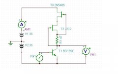
Today I played also with this CCS, its stability/thermall independency is remarkable, certainly usable for many types of amps.
Regards, Andrej")
I didn't have a spice model of the TL431, so I wasn't able to sim this version.
I didn't have a spice model of the TL431, so I wasn't able to sim this version.
Try to replace TL431 with 2,5 V battery (DC voltage source).
Try to replace TL431 with 2,5 V battery (DC voltage source).
OK, I didn't have the time to look up what it was. I'm busy now since I'm back in the 'states and have to catch up with work.
I graphed mine differently - simply showing how well the CCS's resisted current modulation
To me best overall performer, considering modulation supression and phase shif is CCS probe 3, the golden mean, best linearity.

Take the best ones (highest impedance at lower frequencies) and put a resistor, even a big resistor, in parallel. Notice what happens to the phase shift. It gets very small all of a sudden. This is because the equivalent output capacitance is small. The RC time constant is short even for large resistors. This is a desireable result.
It has nothing to do, to first order, with the "speed" of the parts. It's simply an issue of a time constant. Eventually, at rather high frequencies, the effectiveness of the various bootstrapping schemes begins to fail, and then you have a "speed" issue.
And again "linearity" is a misnomer. The term should be constancy or flatness with frequency. A straight horizontal line represents something that is constant as a function of the independent variable (in this case, frequency). This is far more restrictive than a straight line with an arbitrary slope.
Thanks for your feedback Lazy Cat I'll check ur candidate in spice and how it sounds.
hi bcarsp - are you suggesting the resistor you mention remains in place or was it to prove a point ? - actually your points were not that clear to me - did you deciide which CCS you prefer ?
mike
hi bcarsp - are you suggesting the resistor you mention remains in place or was it to prove a point ? - actually your points were not that clear to me - did you deciide which CCS you prefer ?
mike
Thanks for your feedback Lazy Cat I'll check ur candidate in spice and how it sounds.
hi bcarsp - are you suggesting the resistor you mention remains in place or was it to prove a point ? - actually your points were not that clear to me - did you deciide which CCS you prefer ?
mike
I'll show an example in a moment. The resistor I'm talking about is more as a thought experiment, and it would be in parallel with a given CCS.
People have been concerned about phase shifts and impedance decreases with frequency, and I've been trying to suggest if things are really high, these are not conerns in real circuits. And certainly not a problem with "linearity" when that term is used properly.
I do like the use of the enhancement-mode FETs in your "ring of two" though. The built-in voltage allows a larger resistance in the source (compared to the implementation with bipolars) and helps output performance to begin with. One concern for some apps: the low-frequency noise of MOS is notoriously variable depending on details of the process, but modern FETs are pretty decent. I haven't played with actual ZVN3306 parts as yet but the are probably pretty quiet. Diodes Inc./Zetex doesn't spec this afaik.
Brad
Has anyone bothered to actually simulate a VAS with these various CCS's? I'm doing that now and I'm finding that some of the ones with higher rejection cause higher distortion in the output. Sometimes, in spite of really high gain for some them, the distortion is lower. It's not clear to me how this is working. Further, with an ammeter in series with the VAS, the rejection is a certain dB below the output level and not an absolute value. This one, for example, has huge distortion with huge rejection (over 100dB).
Attachments
Last edited:
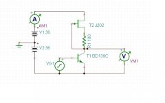
And this one does not. Go figure. I don't know why yet. I mean, the difference is 100 times in distortion for the same input and in spite of the fact that this one has more gain and is running at about the same current as the other one. This one has about 70dB of gain and the other one about 30, and the other one has far more distortion!
Attachments
Make sure to compare as a point of reference a circuit with an ideal current source. This will help disentangle the CCS effects from other effects.
And also be sure to make the comparisons at comparable output levels. Higher gain (due to a higher-Z CCS) should at low frequencies allow smaller input signals. A bare bipolar as shown in your two circuits is a great distortion generator when driven from a voltage source (especially). A little bit of emitter degeneration will help a lot and also raise input impedance.
And also be sure to make the comparisons at comparable output levels. Higher gain (due to a higher-Z CCS) should at low frequencies allow smaller input signals. A bare bipolar as shown in your two circuits is a great distortion generator when driven from a voltage source (especially). A little bit of emitter degeneration will help a lot and also raise input impedance.
Make sure to compare as a point of reference a circuit with an ideal current source. This will help disentangle the CCS effects from other effects.
And also be sure to make the comparisons at comparable output levels. Higher gain (due to a higher-Z CCS) should at low frequencies allow smaller input signals. A bare bipolar as shown in your two circuits is a great distortion generator when driven from a voltage source (especially). A little bit of emitter degeneration will help a lot and also raise input impedance.
I tried replacing the voltage generator with a current generator and I can't get it to function. I get negative gain.
If I drive the lower gain circuit with more voltage to get the same output as the higher gain one, the distortion will be even greater.
I tried replacing the voltage generator with a current generator and I can't get it to function. I get negative gain.
If I drive the lower gain circuit with more voltage to get the same output as the higher gain one, the distortion will be even greater.
Replace the current source load with a ideal current source. Adjust the current to center the output voltage (it will be very sensitive). Continue to drive the base with the same source you use for the other circuits, reducing the drive voltage to restore the same output signal. We're trying to answer the question: What is the effect of the current source load?
Replace the current source load with a ideal current source. Adjust the current to center the output voltage (it will be very sensitive). Continue to drive the base with the same source you use for the other circuits, reducing the drive voltage to restore the same output signal. We're trying to answer the question: What is the effect of the current source load?
OK, thanks. I am doing that but I get strange results. If I try to lower the current to make the collector near zero volts, the gain goes way down and distortion goes up. Sometimes, I get a collector voltage that is more than the battery supply! I think Tina is confused... I don't have time now to mess with it.
The ideal current sources in most simulators don't care about what voltage they are referenced to. I just connect mine to ground, unless the current does flow out of "both ends" in the given circuit, despite the violence to intuition. So yes, you can get arbitrarily high voltages.
Has anyone bothered to actually simulate a VAS with these various CCS's?
I tried just that earlier today and my conclusion is that the best CCS design could depend very much upon the amp's topology.
For a zero loop feedback design things may be very different and lazy cat's choice may be best for the application he has been designing in SSA recently but my current design is a fairly high FB design with the emphasis on speed & stability - and for this design I could not find a CCS that performed any better than the "probe 9" version I presented earlier. I tried transient, fourier, AC open loop, closed loop & PSNRR and in these regards none could better this version.
The shear bandwidth & the massive PSNRR seem to win out - ahhh feedback does make some aspects of amp design very simple ( and others very tricky ! )
I would assume that we would want the lowest distortion VAS, provided it has enough gain, regardless of the amount of feedback applied, since feedback only reduces distortion in a proportional and not an absolute amount.
Actually I just tried it.
Regarding PSNRR & square waves into 8R + 100nF the results between ideal CCS & my "probe 9" were identical.
However with Fourier: The "probe 9" CCS gave much more higher order even cancelation that the "ideal" CCS - opposite of what you suggest ! or was that what you suggested ?
Not worried though - I already love the sound of this amp and the only difference I could identify between "probe 9" and what I'm currently using ( "probe 1" ) is better PSNRR & marginally better stability - If I hear a difference I will be amazed but who knows !
Last edited:
- Status
- This old topic is closed. If you want to reopen this topic, contact a moderator using the "Report Post" button.
- Home
- Amplifiers
- Solid State
- Best VAS?