Another Favorite?
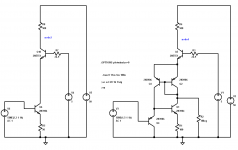
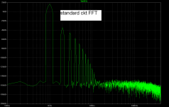
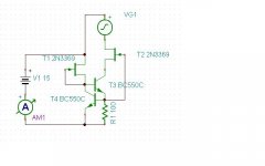
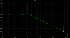
Here's a favorite of mine...It's based on an old patent by Milt Embree. Notice from the plots how wonderful the suppression of the high harmonics is. I've made both stages with about the same total current in the 500 Ohm resistors, and pretty much the same gain.
I have never put this in an amp as a Vas, but I've always figured it could be a good performer.
Attachments
Here's a favorite of mine...It's based on an old patent by Milt Embree. Notice from the plots how wonderful the suppression of the high harmonics is. I've made both stages with about the same total current in the 500 Ohm resistors, and pretty much the same gain.
I have never put this in an amp as a Vas, but I've always figured it could be a good performer.
Are the voltage sources in those models zero impedance? It would be interesting, if so, to see the predicted performance with some impedance in series.
It does look intriguing though, with the input device's current rising with the positive signal and with what amounts to a current gain of two from the mirror, something I've done with sets of cascaded mirrors. I'll have to study it further. Thermal distortion looks like a (soluble) problem.
Brad Wood
Lazy Cat CCS 1a
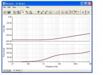
Hi Lazy Cat, here are the results from my sim of your circuit 1a. It has really great bandwidth, but only about -95dB of suppression. There always seems to be a trade off between bandwidth and suppression (or negative gain I guess you'd call it). I don't know which is better or more desirable.
Hi Lazy Cat, here are the results from my sim of your circuit 1a. It has really great bandwidth, but only about -95dB of suppression. There always seems to be a trade off between bandwidth and suppression (or negative gain I guess you'd call it). I don't know which is better or more desirable.
Attachments
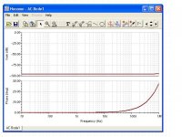
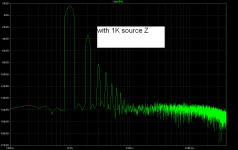
Here's a sim with 1K of source impedance.
As I suspected the circuit has high frequency peaking with that source impedance, easily tamed with a capacitor to common at the input (for my sim, about 5.6pF flattens things nicely for a 1k source resistance).
Unfortunately it looks like reducing thermal distortions is incompatible with the basic distortion spectrum behavior. There may be yet a way. One observation: the distortion is associated almost entirely with the lower quad of devices, and the common base stage contributes little by comparison.
The nondegenerated current mirror will worsen noise performance, although depending on its location in some overall circuit, this could be a small effect.
Oh shoot, I screwed up sorry. I had the wrong jfet's in there. This is screaming good.
Dirkwright, thanks for the sim.
")
Yeah AC performance is extraordinary, will practically test it soon.
Today I played also with this CCS, its stability/thermall independency is remarkable, certainly usable for many types of amps.
Regards, Andrej
Interesting to see the VAS model independent. I need to pull out the ones I have been playing with. What I find relevant is in the rate the harmonics fall off. Of the amps my wife can't tolerate, the overall distortion is lower, but the harmonics remain at about the same level, say 100 dB from about third on out, where the few she can, fall off basically following the noise floor. Of course, these models have perfect sources. Modeling the complete stage may be more informative.
just trying to confirm what you said.
A higher distortion amplifier that has a low proportion of the higher harmonics sounds nicer than a lower distortion amplifier with a higher proportion of the higher harmonics, to your wife.
Is that correct?
Can you hear a difference?
A higher distortion amplifier that has a low proportion of the higher harmonics sounds nicer than a lower distortion amplifier with a higher proportion of the higher harmonics, to your wife.
Is that correct?
Can you hear a difference?
Here's a favorite of mine...It's based on an old patent by Milt Embree. Notice from the plots how wonderful the suppression of the high harmonics is. I've made both stages with about the same total current in the 500 Ohm resistors, and pretty much the same gain.
I have never put this in an amp as a Vas, but I've always figured it could be a good performer.
Is the Embree patent 4,354,122, "Voltage to Current Converter"? That one is the closest I could find.
In any case, and this is probably discussed in the patent, the drawbacks of the circuit are (1) thermal problems, i.e. signal-induced shifts in operating point and gain, (2) as presented, distortion in the current mirror, and (3) distortion arising from the loading of the source impedance.
Otherwise, the basic idea of compensating a base-emitter voltage drop with another one that tracks the current is very clever and effective, especially if massaged a bit.
By prefacing the stage with a good unity-gain buffer problem 3 is made negligible, albeit with adding parts. A better current mirror handles problem 2 (for example the Wilson mirror shown in -122). We are left with the large excursion of input transistor dissipation.
Placing a resistor in the collector can reduce this. But the most desirable situation is to have the dissipation shifts of both devices track, and this can be achieved with an additional common-base stage driven from the 100 ohm resistor with a certain voltage offset, and another resistor between the NPN collector to the CB stage emitter. Presuming the transistors are good complements thermally as well as electrically, problem 1 is fairly well solved.
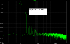
Simulations indicate some very promising results, especially considering the large current swings as a fraction of quiescents, and the falloff of higher harmonics is preserved. Almost worth building!
I may work up a simplified schematic of an example.
Brad
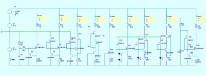
Example after Embree
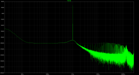
The plot of the distortion spectrum is a bit difficult to read because of the obscuring grid lines. I've marked the 3rd with one of the cursors, about 98dB below the fundamental of 1kHz. 6th is at about -135dBr. The signal in is 2V p-p, output 20V p-p. The results are for a unity-gain amplifier of some moderate complexity but of negligible contribution to the distortion for a 1kohm source resistance. The one I used has a bit of additional peaking due to a negative input Z component.
The dissipation changes of Q1 and Q2 approximately track with signal swing. E96 values are shown for resistors although some residual tweaking could help a little. The Boxall configuration (Q3, Q4) of the common-base output is not on the face of it particularly helpful for distortion, but does make the shifts due to beta changes in Q3 small.
Although I haven't finished playing with the frequency response, it's out around 70MHz for a low Z source (25 ohms, omitting the buffer amp) with a teensy bit of peaking. To get that performance in a build probably will require SM versions of most of the transistors and a very tight layout. Embedding this stage in an amplifier as a transconductance with capacitive feedback would also be intriguing.
Brad
Attachments
just trying to confirm what you said.
A higher distortion amplifier that has a low proportion of the higher harmonics sounds nicer than a lower distortion amplifier with a higher proportion of the higher harmonics, to your wife.
Is that correct?
Can you hear a difference?
100% yes to the wife test, maybe 70% confidence myself. That is not enough to be sure. I think I hear the edgy sound, and it correlates to two other tests I can hear. Too close to call. It actually causes pain to her.
I hear several differences clearly, but none that specifically bother me. The improvements to the Hafler 120 reduced the "metallic" string sound of a Julian Bream recording, and it has more detail. Not as much as the Parasound 1200 which also failed the wife test. So the working theory is it is the high order harmonics causing tweeter issues. The next test will be a steep low pass or notch in the crossover. In the mean time, the Hafler is happy in my office where adding a real preamp (CA-5 Nak) and the improvements made have breathed some life into what I considered to be pretty dull Kef Q1's. Let's be clear, the "failing" amps are all very good units of high regard.
It seems we are in a realm where a very good amp does not mask issues of not so good speakers, where the Rotel was built knowing it would be used with mid-line speakers, so it somewhat masks these problems. I wish I could talk to whoever designed the Rotel 8 and 9 series amps to see if that theory holds. Of course, corporate politics would never let them admit it. I consider the older Rotels to be like a well worn pair of shoes. Comfortable. Not perfect, but comfortable. Kind of like the only speaker she liked, the Vanderstein 2ce. They do a lot of things right, but their biggest attribute is not doing anything wrong. Easy to live with. Well, too ugly for the living room.
So, depending on how the notch filter comes out on some test speakers, I may add that to the Studio 20's to see if that makes the "better" amps acceptable. If not, I am back at square one in what the difference is. She can hear it, every time with total reliability, so it should be measurable. This is the second difference I can point to. The first is how the cone behaves when started from rest with a perfect 3 cycle pulse. The cone was slower to catch up with the drive than the Rotel in spite of the far better damping factor and a bit more power. I have not re-run this test after the Hafler was rebuilt with the symmetrical slew rate.
And a lower harmonic distortion amplifier with lower proportion of higher harmonics ( this is nearly always the case) ???
Not enough samples to know. She likes both the RB 951's and RA 840's. Failing are the Hafler 120 and 220, HCA 1200, B&K 120, Aimor, KH 300 elite, Meng, and everything else I have owned or listened to. ( several dozen) I have not put my little Creek on the line yet. I have not modeled all of them and only measured a few. Measurements follow the model in shape, but a lot worse. Surprise surprise.
Oh, the lower noise floor of the 120 from my mods made a clear difference to me, but had no effect on her. 8 to 12 dB measured.
Brad,
"Is the Embree patent 4,354,122, "Voltage to Current Converter"? That one is the closest I could find."
That looks reasonable...I worked with Milt some, way back when, and the timing seems about right. I never did see the patent...Milt had showed me the circuit while the patent was pending.
It looks like you've added some finesse to the basic scheme! I'd be quite curious about your eventual results in an amp. As I mentioned, so far, it's been a cute circuit that I've used from time to time in other applications, but haven't yet put it into a VAS.
All the best...
Dan
Update My Dynaco
Brad,
"Is the Embree patent 4,354,122, "Voltage to Current Converter"? That one is the closest I could find."
That looks reasonable...I worked with Milt some, way back when, and the timing seems about right. I never did see the patent...Milt had showed me the circuit while the patent was pending.
It looks like you've added some finesse to the basic scheme! I'd be quite curious about your eventual results in an amp. As I mentioned, so far, it's been a cute circuit that I've used from time to time in other applications, but haven't yet put it into a VAS.
All the best...
Dan
Update My Dynaco
Clearly a great and astute designer. Thanks again for pointing me to it.
Brad
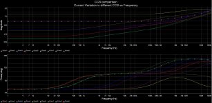
here is a plot of differnt current sources (led/Bjts and Jfet) and their output impedance's.. Common is that a jfet cascode or dual JFet cascodes really makes things a lot better....
I Just found this post when it was referenced in another thread and decided to check the CCS in my DC linked fetzilla which I call "SMA" - Simple Mosfet Amp.
I was happily surprised that mine appeared out perform all of those shown so I went on to include all the designs I know.
I chose 10 - 12 mA as the constant current but as your Jfet design was not happy at that current I halved it.
Several of the designs I included appeared to outperform your design ( probe 4 ) but I suspect it was not optimised for this higher current.
The last design on the far right ( probe 9 ) was my best effort - marginally better that the one I am using which is also very good ( probe 1 )
I did try a Jfet o/p cascode on the probe 9 cct but when I actually spiced this in my amp cct in a transient sqaure wave test into 100nF + 8R load it make absolutely no difference so I dropped it again. The probe 9 cct also has excellent PSNRR.
I graphed mine differently - simply showing how well the CCS's resisted current modulation
p.s. Probes 2 & 9 results are similar colours and convergent until about 400Khz - sorry, that is not very clear
Attachments
Last edited:
- Status
- This old topic is closed. If you want to reopen this topic, contact a moderator using the "Report Post" button.
- Home
- Amplifiers
- Solid State
- Best VAS?