jcx said:the IRL3103 mosfet i used in my sim earlier in this thread has lower on voltage than most suitable bjt at the ~6-8 A that you might use in this amp (and that’s looking at ic/ib = 10 bjt saturation curves)
low on-voltage loss is the key, in my view. mosfets are more rugged than bjts, and don't suffer from 2ndary breakdown (for the most part) and handle large current very well.
However,most of them have high on-voltage losses. so the key is to find something like IRL3103 (I haven't seen its datasheet) that have low on-voltage loss then you are in.
Hi LineSource, jcx and jam,
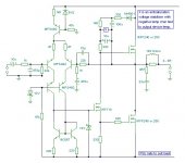
Attached is the Bengt Olssen circuit published in Electronics World and Wireless World p992 Dec 1994.
Article 'Better Audio from non-complements?' is copyright. Patent status unknown.
Bengt quotes 20V.rms 4R 10kHz 0.01% distortion with an emitter follower between input stage and the VAS IRF710, but he does not show it on the circuit.
This is the same current as 25W 1 ohm, and from one pair of Mosfets.
Hi Millwood,
This must be similar to the output stage you modelled. This has voltage drive and saturation limiting thus it runs into gradual crossover class-AB without blowing output devices with overload or switch-on.
AB operation means that it can better power into a capacitor.
You reported the current driven JLH class-A becoming muffled when paralleled with 1uF.
The load was causing slew rate limiting in the same way that loudspeakers momentarily can with class-A biasing. Hence my earlier comments.
When the quiescent current remains the same, but transistor headroom is increased, the reactive load driving capability is available to higher frequency because hf gain does not droop away as quickly. Not greatly, but for all the cost of just a few volts, this is why I now use 5V throughout my class-A work. ( I don't build class-B) This choice of headroom allowance has nothing to do with saturation, close to which an audio frequency bipolar amplifier should not be run in order to ensure linearly operating NFB loop control.
Only explaining my thoughts, not sparring.
Cheers for now............. Graham.
Graham Maynard said:This must be similar to the output stage you modelled.
Cheers for now............. Graham.
I thoughtyou guys had concluded that such a topology like this could never work, in spite of the fact it sounds so wonderfully in the real world,
")
yes, the output stage is identical to my mosfet impersonation of the JLH1969 circuit.
while it is "sad" that I couldn't lay the first claim on this circuit, it is comforting to know that some real experts thought it would work years before I did,
.Hi Millwood,
Yes Millwood I openly admit that I said it would not work, meaning as a satisfactory loudspeaker driving 'audio' amplifier, as opposed to a resistor driving 'audio frequency' amplifier.
Don't be miffed, you might come to understand why my thinking has become quite different to other folks.
I would never have built this circuit because it is flawed by the inclusion of an output choke.
The figures quoted are for steady state sinewave distortion with resistor load.
These do not impress me because they do not cover the amount of distortion that occurs on the first cycle of any waveform.
Bengt went on to a balanced non-complementary output stage after this was published.
You might not have used a choke in your own personally developed circuit, but you would then have had to use other components to maintain stability.
Can your simulator give a reading of the distortion of your circuit to a single first cycle at 10kHz with resistor load ? I should be very interested to know.
Another aspect is that output Mosfet junction capacitances not only imbalance the push-pull voltage drive presented by collector and emitter (in a way that varies with loudspeaker loading) but also slows the output stage down and degrades NFB control when the load is dynamically reactive. Many Mosfet amps do this to some extent, but altered NFB responses will not be observed during simulation unless the load is modelled upon real world loudspeakers.
____________________________________________________
Hi LineSource,
I still need you to tell me what your load requirement is if you want me to offer a simple, 0.01% @ 10kHz and 25W 'first cycle distortion' class-A circuit. There are very few amplifiers in the world that manage this figure, even those that are specified as 0.001% THD.
If your requirement is purely resistive I am thinking about +/-12.5V @ 6A with 4 output pairs; maybe from two car batteries.
The steady state sinewave distortion at 10kHz 1W 1R is simulating at 0.002%.
Is it one ohm with a tiny amount of series inductance, don't forget cable inductance and resistance ?
Or is it a dynamic driver which would require even greater quiescent current with this *pure* class-A design ?
Cheers ............. Graham.
IGraham Maynard said:
Hi LineSource,
I still need you to tell me what your load requirement is if you want me to offer a simple, 0.01% @ 10kHz and 25W 'first cycle distortion' class-A circuit. There are very few amplifiers in the world that manage this figure, even those that are specified as 0.001% THD.
Cheers ............. Graham.
Graham,
Thanks for contributing.
My particular application is a ribbon linesource with 0.9 ohms resistance plus 12 feet of 10 AWG wire going down the ribbon side and to the amp. The inductance is very small. Since the ribbon is in a strong magnetic field, there will be a very small reverse emf voltage. The ribbon is 100db/watt efficient, so the amp must be extremely low noise.
Step up transformers do not give a stable sound stage. The best solution has been to construct a non-inductive resistor and pad the load up to 2-3 ohms. For class A low noise, this approach means a big amp instead of a cute box at the speaker.
I hoped the diyAudio amp experts would take up the challenge and come up with a very low noise design that all ribbon and planar designers could use, since these transducers are quickly getting better and cheaper.
Graham Maynard said:Yes Millwood I openly admit that I said it would not work,
well, while your admission isn't a perfect one, you at least have the courage to admit your fault, far better than a few others who fought along with you,
I think that discussion is very interesting from the point of view that a lot of "experts" throw a lot of magic words and wonderful theories of why the mosfet jlh1969 would not work.
I am sure those guys have tons of training in electronics and the like and I am sure there are plenty of cases where their point of view is proven correct.
however, electronics, like in banking, is an art where one has to find the most dominating factor and ignore the rest. The real experts are those who can identify the key factor(s) and not get confused by the not-so-important ones.
The also-runs unfortunately get all confused by the 2ndary factors and never to get understand what is important and what isn't.
The fact that you didn't figure out from day one that it worked is quite disappointing, your credential not withstanding.
meaning as a satisfactory loudspeaker driving 'audio' amplifier, as opposed to a resistor driving 'audio frequency' amplifier.
Cheers ............. Graham. [/B][/QUOTE]
That's a good point, but am I not sure I have seen enough to get convinced that there is a substantial difference between a real speaker and a pure resistive load.
to me, it sounds more like marketing than anything else, like those "zero feedback" amps,
.If you have anything to the contrary, i am all ears.
for starters, i would suggest that we compare simulations of an amp driving resistive loads with the same amp driving a "simulated" speaker load (thiele model for example).
Anyone wishing to try?
I thought about this for a while. for a real speaker, its impedence goes up with frequency (as the serial inductance takes over at higher frequencies).
This would means that power output on the serial resistor (kind of like the true output of this rcl network) goes down at higher frequencies. In other words, the gain as measured on the serial resistor goes down with frequency.
there is likely phase angle shift, again, measured at the serial resistor. I am not sure if phase angle, measured at the whole rcl network, will be materially different from that on a pure resistor.
But it is just my guestimate,
Hi Millwood,
FAULT ?
Millwood. Does someone who has different ideas to you necessarily suffer from faulty thinking ?
Text books often need to be updated as well !
This IS an AUDIO site, isn't it ?
You might be frustrated at being unable to see another person's point of view, or even find it difficult to accept that they are allowed to hold such a view if it helps them on their way, but that does not automatically give you a personal right to ACCUSE them. Occasionally some folks can go so far over the top with a tunnel vision on insignificant matters, that they lose sight of the bigger picture _ how the dynamically reactive loudspeaker is driven in real time by complex waveforms that are not even symmetrical.
I have tried to explain, and from your second post I can see that you are thinking about what I have written, but the loudspeaker back emf problem is much more significant than just thinking about passive inductance and capacitance.
The loudspeakers and their components momentarily store energy as currents flow, due to conservation of energy fundamentals the subsequent release of this energy causes reflections to occur after the energising wave has passed, which can react with the amplifier as it attempts to maintain its low impedance output wrt on-going signal input. This is why all amplifiers sound different when their distortion specifications are one hundred times better than humans are capable of discerning.
It is also why bi and tri-amping sounds better because back emfs from one driver can not upset the potential to another, most notably the tweeter.
Any propagation delay within the amplifier allows the ouput terminal voltage to shift minutely, and sometimes very sharply before the NFB loop can properly correct it. Mosfets can introduce significant propagation delays unless their gates are driven at low impedance.
I asked a significant question;- Can your simulator show up first cycle distortion; ie. is it concealing from you everthing you need to know _ _ propagation delay within the first cycle ? If it can show this;- What was the first cycle distortion of your circuit ? You might be surprised !
You continue to suggest simulating amplifiers with a resistor load, but we don't listen to RESISTORS ! Only trying to explain.
Hi LineSource,
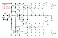
I have no qualms about recommending this simple pure class-A circuit for your ribbon driver.
Rb should be adjusted to set up the quiescent current, which may or may not need to be adjusted according to your choice of output devices. This relates to the junction capacitances, not static DC gain. Maybe you could simulate with all your own intended components before you construct.
You may reduce the C values to shift the high-pass turnover because this is flat phased (+/- 2 degrees) from approx 12Hz to 50kHz.
Cheers for now ........... Graham.
FAULT ?
Millwood. Does someone who has different ideas to you necessarily suffer from faulty thinking ?
Text books often need to be updated as well !
This IS an AUDIO site, isn't it ?
You might be frustrated at being unable to see another person's point of view, or even find it difficult to accept that they are allowed to hold such a view if it helps them on their way, but that does not automatically give you a personal right to ACCUSE them. Occasionally some folks can go so far over the top with a tunnel vision on insignificant matters, that they lose sight of the bigger picture _ how the dynamically reactive loudspeaker is driven in real time by complex waveforms that are not even symmetrical.
I have tried to explain, and from your second post I can see that you are thinking about what I have written, but the loudspeaker back emf problem is much more significant than just thinking about passive inductance and capacitance.
The loudspeakers and their components momentarily store energy as currents flow, due to conservation of energy fundamentals the subsequent release of this energy causes reflections to occur after the energising wave has passed, which can react with the amplifier as it attempts to maintain its low impedance output wrt on-going signal input. This is why all amplifiers sound different when their distortion specifications are one hundred times better than humans are capable of discerning.
It is also why bi and tri-amping sounds better because back emfs from one driver can not upset the potential to another, most notably the tweeter.
Any propagation delay within the amplifier allows the ouput terminal voltage to shift minutely, and sometimes very sharply before the NFB loop can properly correct it. Mosfets can introduce significant propagation delays unless their gates are driven at low impedance.
I asked a significant question;- Can your simulator show up first cycle distortion; ie. is it concealing from you everthing you need to know _ _ propagation delay within the first cycle ? If it can show this;- What was the first cycle distortion of your circuit ? You might be surprised !
You continue to suggest simulating amplifiers with a resistor load, but we don't listen to RESISTORS ! Only trying to explain.
Hi LineSource,
I have no qualms about recommending this simple pure class-A circuit for your ribbon driver.
Rb should be adjusted to set up the quiescent current, which may or may not need to be adjusted according to your choice of output devices. This relates to the junction capacitances, not static DC gain. Maybe you could simulate with all your own intended components before you construct.
You may reduce the C values to shift the high-pass turnover because this is flat phased (+/- 2 degrees) from approx 12Hz to 50kHz.
Cheers for now ........... Graham.
Attachments
LineSource said:I
Graham,
Thanks for contributing.
My particular application is a ribbon linesource with 0.9 ohms resistance plus 12 feet of 10 AWG wire going down the ribbon side and to the amp. The inductance is very small. Since the ribbon is in a strong magnetic field, there will be a very small reverse emf voltage. The ribbon is 100db/watt efficient, so the amp must be extremely low noise.
Step up transformers do not give a stable sound stage. The best solution has been to construct a non-inductive resistor and pad the load up to 2-3 ohms. For class A low noise, this approach means a big amp instead of a cute box at the speaker.
I hoped the diyAudio amp experts would take up the challenge and come up with a very low noise design that all ribbon and planar designers could use, since these transducers are quickly getting better and cheaper.
Regarding low noise :
I can't comment on the high tech approach involving a low noise
op-amp and driver circuitry running off regulated 15-0-15W rails
with ouput MosFets running off say 9-0-9V rails, I'm not a fan
of IC's or Mosfets (in normal aB amplifiers), but I'm sure it could
be valid approach, depending on opinion of feedback topologies.
D.Selfs "Audio Power Amplifier Design Handbook" contains a
wealth of useful information even if you don't agree with some
of his conclusions, I highly recommend you obtain a copy
It does cover noise performance in detail and also shows that the
limiting factor in noise performance is the pre-amplifier at normal
volume settings and attention should also be directed here.
D.Selfs standard topology has PNP input transistors for low noise
and he also shows how to bootstrap the input for even lower
noise, IMO usually (due to the pre-amp) this is not necessary.
What his book also shows is its not that difficult, if fact quite easy
to build a BJT amplifer that when connected up will work quite well.
The circuit posted by GM will work quite well, but its merits or lack
of them to an extent depend on the power supply regime you
use, as its stands ripple rejection doesn't look good, but as a
treble only amplifier I'm not sure how important this would be.
DS's basic circuit is not too different from that posted by GM
and I'd recommend using his input and voltage gain stage
but with a similar bias stage and similar output stage.
(edit : I'm not sure if combining the voltage gain and driver
stage is a good idea here, perhaps others could comment ?)
Ripple rejection of these two stages (which appear to be
the only two that matter) is in covered in detail, as is how
to optimise their performance in all other areas.
Note that as treble amplifier very high quality lower
value capacitors can be used in the feedback loop.
Your load is very nearly purely resistive.
I'd be interested in what other drivers there are and what is
driving them to arrive at a maximum SPL figure. 25 watts into
100dB/W above 3Khz is a considerable SPL capability, as its
equivalent to using a 250W amplifier for a 90dB/W treble unit.
sreten.(P.S. not an "Expert", which is why I like the simpler stuff)
Hi sreten,
So my circuit suggestion will work,
BUT ONLY "quite well".
Sreten, you have me shaking my head here.
I thought you might have simulated it, before commenting.
Noise is circa minus 115dB at 1kHz.
I don't think you'd hear that, even with 90dB drivers.
I couldn't hear ANYTHING on my 8 ohm prototypes.
There was no start up thump.
No hum.
No hiss.
Just clean and delightfully clear music !
In fact I thought that my prototype was faulty when it got the - 'right this is it' - 'I'm ready for anything' - first switch-on.
Where is the rail hum supposed to get in ?
Either there is capacitor filtering, or an isolating high impedance leg.
In view of your comment, I've just run a check on both rails. They reject to minus 66dB, so as long as the ripple is below a relatively poor 1Vp-p, you really won't be hearing anything.
I wonder what you mean about combining the 'voltage gain' and 'driver' stage.
My circuit uses a mirrored differential voltage to current input stage, driving a current to voltage output stage; the BD139 is an integral part of the current driven output stage, as in the JLH designs. This is an inherently stable two stage design, and embodies the widely respected characteristics of that early JLH design.
From what I have seen of D Self's circuits, they are three stage and not inherently stable, which is why he uses a Miller connected C.dom plus circa 5uH of series output choke, *which cannot be used with a 0.9 ohm ribbon tweeter*.
____________________________________________________
LineSource,
I've just done a check. 5uH in series with your 0.9 ohm module will lead to 20 degrees of phase shift at 10kHz. Maybe you could shorten the interconnecting leads too, because 12 ft will have quite an inductance, and thickness has little effect upon that.
Could it be that you have used long leads to feed a composite loudspeaker plus the tweeter matching transformer. Cable inductance would cause music induced interaction between loudspeaker drivers and crossover circuitry at the cable end. You would not believe the effect this can have until you check it out for yourself.
Did you try running the treble unit transformer directly from your amplifier using a sparate cable ?
Is your amplifier fitted with an integral series output choke, if yes I won't say bin it, but don't use it for 8 ohm treble unless separately as in a bi or tri amped system. Output chokes ruin audio when they are loaded by multi driver loudspeakers other than line sources and full range drivers.
___________________________________________________
That is a good amplifier circuit; simple too. I have designed it for 25W into 1 ohm, but it might run louder.
___________________________________________________
Any other circuit suggestions ? Anyone ?
How do you figure? I count a minimum of three junctions between input and output.This is an inherently stable two stage design
Graham Maynard said:I have tried to explain, and from your second post I can see that you are thinking about what I have written, but the loudspeaker back emf problem is much more significant than just thinking about passive inductance and capacitance.
How is the back EMF of a loudspeaker fundamentally any different than the back EMF of a RLC resonant circuit?
The loudspeakers and their components momentarily store energy as currents flow, due to conservation of energy fundamentals the subsequent release of this energy causes reflections to occur after the energising wave has passed, which can react with the amplifier as it attempts to maintain its low impedance output wrt on-going signal input.
Reflections? What reflections? How do you get any reflections to speak of between the relatively short distance between an amp and a loudspeaker when the wavelengths involved are many miles long?
Sure you don't mean ringing? If so, how is the ringing of an underdamped loudspeaker fundamentally any different than the ringing of an underdamped RLC circuit?
se
Sure you don't mean ringing? If so, how is the ringing of an underdamped loudspeaker fundamentally any different than the ringing of an underdamped RLC circuit?
It isn't.
pinkmouse said:Surely the effect of the mechanical aspects of the loudspeaker will have an effect on back EMF, after all, the VC is a generator under the control of a cone that has it's own mechanical resonances?
But the electrical and mechanical resonances still add up to a resonant system.
You have QMC which represents the driver's mechanical resonance and QEC which represents the driver's electrical resonance.
These combine to a singular resonance, QTC, by way of:
QTC = (QMC x QEC) / (QMC + QEC).
It's not just straightforward LRC...
Then why is the fundamental behavior of a loudspeaker driver modeled as an RLC resonant circuit?
se

Graham Maynard said:Hi sreten,
So my circuit suggestion will work,
BUT ONLY "quite well".
.....
I wonder what you mean about combining the 'voltage gain' and 'driver' stage.
.....
From what I have seen of D Self's circuits, they are three stage and not inherently stable, which is why he uses a Miller connected C.dom plus circa 5uH of series output choke, *which cannot be used with a 0.9 ohm ribbon tweeter*.
Hi GM,
Sorry I didn't mean to "damn your circuit with faint praise"
if that how it appears, it wasn't intended but thats my fault
for using "quite well" in two consecutive paragraphs, and
I really shouldn't have had them as consecutive paragraphs
either, it reads as though I'm saying something I didn't mean to.
I notice the LTP tail is RC decoupled, but therectically a
current source tail would be better, but treble only ?
Suppose here its a choice of current sourcing both the tail and
driver stage, or RC decoupling and bootstrapping as you have
done, I can't say which is better, only "theorectically".
Just note theorectically the feedback shouldn't
share the same ground as the decoupling point.
.....
As you say its a two stage amplifier.
.....
And yes you certainly can't use a "standard"
output inductor value for a 0.9R output load.
sreten.- Status
- This old topic is closed. If you want to reopen this topic, contact a moderator using the "Report Post" button.
- Home
- Amplifiers
- Solid State
- best topo for 25W class A into 1 ohm resistive load?