negative base resistance in EF
Greetings traderbam,
I assure you that John Curl has answered you correctly. The link below is an explanation of the cause of negative resistance in emitter followers that I posted recently in another thread. The post was a response to questions you raised, regarding emitter followers and feedback. A good reference text if you wish to see the full math derivation is "Pulse, Digital, & Switching Circuits", by Taub and Schilling, c 1965.
I've designed dozens of emitter followers, and I've seen the effect of negative resistance first hand. Local oscillation is the result. The oscillation is suppressed by adding a (positive) base resistor. Adding resistance in the emitter does not cancel the negative resistance seen at the base. The math (condensed) is in the link below. If clarification is needed, I'll do so. Best regards.
Claude
http://www.diyaudio.com/forums/showthread.php?s=&threadid=28764&perpage=10&pagenumber=21
originally posted by John Curl
the reason for a base resistor is to add a POSITIVE resistance to the base of the transistor. This counteracts the NEGATIVE resistance that can appear at the base of a transistor follower with a cap load.
originally posted by traderbam
John,
I don't really understand how you get a "negative" base resistance as a result of a capacitive load. Can you explain?
Can you also explain why you should use a base resistor rather than an emitter resistor?
Greetings traderbam,
I assure you that John Curl has answered you correctly. The link below is an explanation of the cause of negative resistance in emitter followers that I posted recently in another thread. The post was a response to questions you raised, regarding emitter followers and feedback. A good reference text if you wish to see the full math derivation is "Pulse, Digital, & Switching Circuits", by Taub and Schilling, c 1965.
I've designed dozens of emitter followers, and I've seen the effect of negative resistance first hand. Local oscillation is the result. The oscillation is suppressed by adding a (positive) base resistor. Adding resistance in the emitter does not cancel the negative resistance seen at the base. The math (condensed) is in the link below. If clarification is needed, I'll do so. Best regards.
Claude
http://www.diyaudio.com/forums/showthread.php?s=&threadid=28764&perpage=10&pagenumber=21
link dead - here's the explanation
Sorry folks,
The link doesn't seem to be working. Here is an excerpt from my post from a few months ago.
"The hfe at high enough frequencies, becomes complex, having a phase lagging component. Instead of pure real, hfe may be 29 - j40 at high enough frequency. If the load is complex, resistive and capacitive, 50 - j60 for example, the complex impedance is reflected back to the base side can have a negative real part, i.e. -900 - j3800. This is essentially a negative resistance. The result is local instability, since the degenerative or negative feedback, becomes regenerative or positive feedback producing local oscillation. To stabilize, we must cancel the negative resistance by inserting some positive resistance in the base side. Any circuit designer who has used emitter followers (I've used dozens) knows this."
If I might add, the impedance seen at the input, or base, of an emitter follower (EF), due to emitter load Ze (output) is (1 + hfe)*Ze. Since Ze is resistive and capacitive, its imaginary part (reactance) is a negative number. Likewise, at a high enough frequency, hfe has a positive real part, and negative imaginary part. At a specific frequency, the product can have a negative real part, as shown above. This is a negative resistance. The voltage and current are displaced 180 degrees. Adding positive resistance in the base, neutralizes this negative value. I've used it with success. I always include this base resistor whenever I use an EF. I hope this helps. Best regards.
Hi! Linsource! Have you ever built your design?
I'm studying about servo circuit for Slone' topo.What opamp did you use in your design?
When I don't apply feedback , offset voltage is 18V .If I apply feedback ,it is about 256 micro ampere .I think this cause stabileity of my amp.
I'm studying about servo circuit for Slone' topo.What opamp did you use in your design?
When I don't apply feedback , offset voltage is 18V .If I apply feedback ,it is about 256 micro ampere .I think this cause stabileity of my amp.
SERVOS. REV 1 PCB LAYOUT
thanh, I'm using AD8099 opamps for my servo only because I have some on hand. I see AD820AN and OP27 often used for servos.
Most of the semiconductors I ordered have come in and I have soldered up three different input-VAS stages and started tweaking and listening.
1) MAT02/MAT03 complementary differential..current source per diff.
2) JFET-JFET complementary differential..current source per diff
These two keep the servo out of the input signal path by tugging on the current source bias resistors as shown in my "design 2"
3) Stacked JFET-JFET_cascoded input complementary differential as shown in my "design 1"
All three sound different! My ears favor (3) until I hook up the servo opamp, then the sound becomes dull. Matching JFETs is very difficult and time comsuming. I had to purchase parts from two different vendors to get a close match.
I am using modest lab power supplies to drive the breadboard and can only get to 1-2 watts of class A. The breadboard VAS and output bias is very different from the final design.
I've also spend a few hours playing with a PCB layout
Attachments
Re: link dead - here's the explanation
What I don't like about base stopper resistors is that they make the output stage gain even more load dependent (even if the relative nonlinearity might become better).
I have found that quite often a ferrite bead on the base lead will do as good a job as a 22R resistor in stopping local oscillations with highly capacitive loads. The advantage is that the bead acts near the frequency of oscillation and not also in the passband of the amp. From what I have read about those ferrites, they become pretty lossy at several MHz, so they would probably add more resistance than inductance.
Claude Abraham said:Adding positive resistance in the base, neutralizes this negative value. I've used it with success. I always include this base resistor whenever I use an EF.
What I don't like about base stopper resistors is that they make the output stage gain even more load dependent (even if the relative nonlinearity might become better).
I have found that quite often a ferrite bead on the base lead will do as good a job as a 22R resistor in stopping local oscillations with highly capacitive loads. The advantage is that the bead acts near the frequency of oscillation and not also in the passband of the amp. From what I have read about those ferrites, they become pretty lossy at several MHz, so they would probably add more resistance than inductance.
easyamp,
The manuals for many commercial amps say that they are not stable into 1 ohm loads. Using simple P=I^2 R, 1 ohm requires 5 amps of bias and 8 ohms only 1.8 amps for 25 Class A watts.
If you are designing an amp for low impedance, high sensitivity speakers of > 100db/watt, you use can use lower power supply voltages which allows you to use transistor types and circuit topologies that higher voltage designs cannot, but you also have to execute a low noise design that is very linear for the first watt.
A good challenge for diyAudio experts.
From listening to breadboard circuits:
1) A servo directly in the feedback path is audible. Dulls the sound. Reduces the dynamics. A servo that controls bias currents to null DC offset was used.
2) JFETS in the input and VAS have a more natural sound than bipolars.
3) A cascoded VAS changes the tonal balance of the mid-to-high frequencies, highs too strong. A +/- 12V pre-driver power supply supports a single FET VAS and a wide range of servo opamps.
4) For a <1 ohm ribbon, a 7-10V output power supply is very adequate and allows using small 8,200 @16V or 10,000uF @10V low impedance capacitors.
5) Sanken 2SA1216G and 2SC2992G are best sounding outputs.
6) Using a non-inductive resistor to pad the ribbon up to 1.5 ohms sweetens the sound...less edge on some CDs.
7) Ribbon direct drive is far superior to a transformer.... clarity, sound stage stability, dynamics..
Attachments
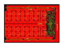
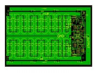
This PCB layout can accomodate all four circuits topos described above.
Any critique of the layout would be appreciated before going to fab. The board is 60 sq inches, approximately 9" x 6.6" to evenly spread the heat on a 12" x 12" heatsink, 2oz copper, $23 protos. With 4oz copper it may be better to put a star power grid on the bottom layer, and signal output star on the upper layer with the circuitry in the center.
Using 8,200uF 16V Panasonic capacitors provices ~ 0.4F for the output supplies.
Attachments
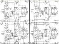
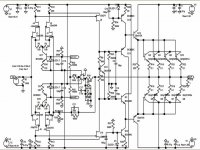
actually the schematic appears as an unreadable group of four
jpg is not the best for lines and text, if you're using paint gif is better, png can also give good compression of line drawings
as for the pcb layout, why not ground plane over pwr and why route large currents in a loop around your lowlevel input circuitry - not as urgent a problem with class A as with class B but still unecessary - just take the output from between the low level circuitry and the output with a pair of heavy twisted wires
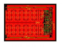
PCB DESIGN 1 TOP LAYER
Top Layer for first PCB design. No jumpers are required. 2 oz copper.
jcx....The output was run around the outside perimeter to bring it close to the input for a good quality feedback path....thinking this was more important than the current induced noise you mention could be a problem.
Top Layer for first PCB design. No jumpers are required. 2 oz copper.
jcx....The output was run around the outside perimeter to bring it close to the input for a good quality feedback path....thinking this was more important than the current induced noise you mention could be a problem.
Attachments
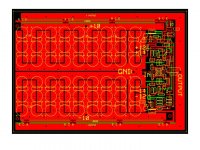
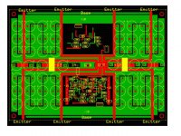
Sketch..alternative PCB design
Unfinished layout of alternative PCB design using star connection of outputs. Three jumper wires probably necessary, including + and - 12 power supplies. 4oz copper may be necessary.
Would this be a better PCB topology for low noise and low distortion?
Unfinished layout of alternative PCB design using star connection of outputs. Three jumper wires probably necessary, including + and - 12 power supplies. 4oz copper may be necessary.
Would this be a better PCB topology for low noise and low distortion?
Attachments
mlloyd1 said:linesource:
any pictures of the final result?
mlloyd1
I built a point-to-point breadboard and learned the following:
1) A servo that adjusts the current sources into the symmetrical input diff pairs is not capable of a deep null... ~50mv still remains. A standard voltage summation servo drops this to just a couple mv.
2) A folded cascode with JFET inputs and Bipolar cascodes gave higher current gain which reduced distortion. In addition, I changed to a full symmetrical topology with push-pull bridged output design. IT SOUNDS FANTASTIC on my Full Range Apogees.
3) I have adapted the Class-A symmetrical-bridged folded cascode to direct drive the 0.15 ohm midrange ribbon using 8 output pairs, and I have completed a 60 sq in PCB layout to hold the two amps plus 12 JFET descrete opamps for LR-8 crossover. I'm experimenting with low level loudness compensation(see post) before I buy PCBs.
4) Sanken 2SA1215Y and 2SC2921Y have become my favorite outputs.
5) The lifetime of small many capacitors(see PCB layout post) is much less than larger computer grade capacitors. If you want a 20 year MTTF, use a few large caps.
6) Experimenting with output protection that uses a shelf opamp at the output of the servo to sense when the output bridge is unbalanced and triggers a DPDT relay that both opens the output power supply and puts a 0.05 ohm shunt across the speaker output. This circuit is also used for a safe power up sequencing. This seems like a good solution when 0.15 ohm speaker loads do not allow a series relay at the output.
- Status
- This old topic is closed. If you want to reopen this topic, contact a moderator using the "Report Post" button.
- Home
- Amplifiers
- Solid State
- best topo for 25W class A into 1 ohm resistive load?