Ribbon amp
Hi,
Elektor magazine had a real nice amp for ribbons a few yrs ago.
Never heard it but it measured really good.
I shall see if I can find that magazine and scan out the schematic if
there is intrest.
I believed they used the 2sc2922 and 2sa1216 outputs, complementary diff input....
/ Mattias
Hi,
Elektor magazine had a real nice amp for ribbons a few yrs ago.
Never heard it but it measured really good.
I shall see if I can find that magazine and scan out the schematic if
there is intrest.
I believed they used the 2sc2922 and 2sa1216 outputs, complementary diff input....
/ Mattias
In response to a question from Thanh, Fab brought up the topic of base stoppers on BJTs.
Mosfets respond well to gate stoppers because without them they can self-oscillate. This phenomenon is well damped by preventing rapid charge migration across the gate/channel interface. Typically a 220R resistor right at the gate connection prevents oscillation. The problem reflects the extremely high input impedance and very high speed of mosfets, which are often caught oscillating at 10MHz or so.
The BJT, on the other hand, is more benign. Since the base junction actually requires current to activate the transistor, and current drive requires relatively low impedance drive compared to the mosfet, charge migrations within the device are not so important. The BJT is not so prone to self-oscillation, but the problem is still ocassionally observed.
Modern BJTs are dropping in cost and increasing in both speed and current capacity. Other constraints on their use are reducing too, such as SOAR parameters. And they are cheaper.....
So, inevitably, BJTs are being used more than ever in audio amplifier output stages. With increasing speed, they are more likely to self-oscillate, too. Since oscillation is a major distraction for an audio amplifier, it robs resolution in the audio band, so we must prevent it. It can even destroy tweeters!
A number of BJT amp designers use base stoppers. They prevent any tendency to self-oscillation, but they do more. They linearise the device to a small extent by increasing input impedance into the device, and making it more 'ohmic'. This means that more collector current requires more base current AND more voltage drive to the base, decreasing transconductance. By making the transistor voltage as well as current driven, we prevent sudden small but non-linear increases in drive voltage, and this can assist with overall linearity, bringing down odd order harmonic generation. It also reduces the feedback factor, all other influences being equal.
Another way of saying this is that small, non-linear voltage drive adjustments require rapid feedback to linearise them. But larger, more linear voltage drive adjustments require slower feedback to achieve the same effect; this reduces the need for very fast feedback networks. Since global feedback is a slowish business, the slower the correction, the lower the distortion AFTER feedback.
Hope this explains it a little; my words are based on listening tests with and without base stoppers. Believe me, the improvement is worth it.
Cheers,
Hugh
"In response to a question from Thanh, Fab brought up the topic of base stoppers on BJTs...."
The linearising effect of transistor with base resistors is confirming what I thought also. It is appreciated that you have "heard" the effect too!
Thank you AKSA for your comment.
Fab
The linearising effect of transistor with base resistors is confirming what I thought also. It is appreciated that you have "heard" the effect too!
Thank you AKSA for your comment.
Fab
It is clear that putting a resistor in series with a device will linearize the transconductance at the cost of reducing it.
A couple of questions:
1) How do you decide whether to put the resistance at the input end (base) or at the output end (usually emitter)?
2) To what extreme can this be taken - how big can the resistor be before the benefit is no more? Eg, why not have a driver stage with +/- 200V swing and 10k base resistors or whatever?
Hmmm. Can't really answer these questions definitively.
First, I find tuning by ear most appropriate here.
Second, there are clear limits to increasing the base stopper. Two which come to mind are noise and operating point stability, but the point at which this occurs is moot. I'd have the notion that voltage drops of the order of the base/emitter voltage might be the limit - that is, at full drive.
Hope this gives food for thought.......
Cheers,
Hugh
AKSA said:A number of BJT amp designers use base stoppers.
Hugh
I think john curl mentioned a while ago that he uses small base stoppers (I thought he said 10ohm).
In my own amps, I use 100-200 ohm base stoppers myself to be able to interchange my designs between bjt and mosfets. no audible difference to me.
LEACH AMP OUTPUT BASE RESISTORS
The latest Leach amp used 10 ohm base resistors on its output transistors, increased from 3.3 ohms in the original design.
A Spice simulation of the 25W/1ohm design in this thread with 3.3 ohm and 10 ohm base resistors mainly shows variations in the square wave response. You get the best rise/fall slopes with no resistors, but get less over/undershoot with base resistors.
For the 1 ohm load design in this thread, a 10 ohm base resistor would have about 40ma max current, 400mV.
MACHINE SHOP PCB
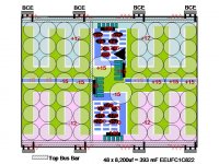
Has anyone constructed a PCB for a power amp by gluing a thick sheet of copper to a fiberglass or Teflon substrate and running it through an XY router in a machine shop? The thick copper would allow mounting the power supply filter capacitors next to the output devices so the entire amp could be on one PCB. The tolerances seem fine for capacitors and transistors, but the 0.1” spaced thru-holes for opamps and D/A chips would be a challenge. A single layer PCB that uses resistors for jumpers and a couple bus bars to connect the NPN/PNP outputs together seems possible. It would also seem possible to build a “generic” PCB this way which could accommodate many circuit topologies.
The attached PCB sketch is for the 25W/1ohm design in this thread. The 8” x 6” PCB with over 400,000 uF would be mounted to a 12” x 12” heatsink.
Is 8 oz copper the thickest PCB copper? What DIY PCB fabs can produce 8 oz copper or thicker PCBs? A two sided 4 oz copper would likely be the standard alternative.
Attachments
Line source,
I did send you some pdfs today from the Elek.ribbon amp.
It's from Oct. and Nov issue of 1992.
Don't want to post them in public. Their agent sits in the building
across the street, huuuh.
Intresting design with a portion of the feedback run from the speaker
terminals.
Personally I would increase the supply from +/- 12 to +/- 15 (Vdc).
btw. For high frequency stuff they are using metal-base boards where
you grow or machine copper as thick as you like and even use for mounting
the semis. Expensive but nice.
/ Mattias
Traderbam, the reason for a base resistor is to add a POSITIVE resistance to the base of the transistor. This counteracts the NEGATIVE resistance that can appear at the base of a transistor follower with a cap load. This is graduate school stuff. Many of us learn it the hard way. Too high a resistance makes parallel transistor matching difficult and slows down the output stage. Too little can cause random oscillations. 10 ohms is a good starting place.
oh! I can't .
When i looking for the datasheet of 2SJ49, i was lucky of watching this site http://www.ne.jp/asahi/evo/amp/Dnfb/details.htm
I posted it up here to discuss .Perhaps it is a good techique which every forgot")
When i looking for the datasheet of 2SJ49, i was lucky of watching this site http://www.ne.jp/asahi/evo/amp/Dnfb/details.htm
I posted it up here to discuss .Perhaps it is a good techique which every forgot
thanh said:oh! I can't ...
...Perhaps it is a good techique which every forgot
you're in great company thanh,
Mason (inventor of "signal flow graphs") analyzed "zero sensitivity" amplifier topologies like this with his new tool but despite generating quite some interest at the time the "infinite" gain from the inner positive feedback loop has remained largely unusable
Horowitz used Bode's phase integral relation to show the limitations of this approach in "Synthesis of Feedback Systems" (1963)
Someone seems to reinvent this technique every few decades since the arithmetic is so inviting - but the fact of the matter is that phase shift is unavoidable and what you really get is at best a (very narrow) gain peak at one frequency
the reason for a base resistor is to add a POSITIVE resistance to the base of the transistor. This counteracts the NEGATIVE resistance that can appear at the base of a transistor follower with a cap load.
John,
I don't really understand how you get a "negative" base resistance as a result of a capacitive load. Can you explain?
Can you also explain why you should use a base resistor rather than an emitter resistor?
a few choice keywords gets this as #1 in a google search:
http://home.tiscali.be/kpmoerman/electronics/notes/efollow/efollow.htm
looks like the right stuff but i haven't read it closely, Linear Technology had a ~30 year old ref on ef oscillation in a earlier catalog CD
http://home.tiscali.be/kpmoerman/electronics/notes/efollow/efollow.htm
looks like the right stuff but i haven't read it closely, Linear Technology had a ~30 year old ref on ef oscillation in a earlier catalog CD
- Status
- This old topic is closed. If you want to reopen this topic, contact a moderator using the "Report Post" button.
- Home
- Amplifiers
- Solid State
- best topo for 25W class A into 1 ohm resistive load?