syn08 said:Guys, I agree that this little regulator is actually more complex than it appears at the first glance. There are literally hundreds of combinations you can build this, and here are a few variables I can quickly think of:
- Bipolar/MOSFET
- Polarity (NPN/PNP or Nchannel/Pchannel, with flipping the opamp inputs)
- Reference type
- Current source to feed the reference (yes, using a resistor to the output or a CCS like a JFET makes a significant difference)
- Ballast resistor or CCS
- Output cap value and ESR+ESL
- Reference bypassing cap value
- Reference bypassing connection (ground/output, yes it makes a very significant difference)
- Other bypassing (control input, like in the Minnesota shunt, yes, it makes a very significant difference).
If somebody with a simulator and enough time could try to optimize and find the best combination of the above, I would be the first to appreciate the effort.
Given the limited time I have, my intention was only to show something that works very good for me (actually probably as good or better than any discrete parallel regulator I can think of, at a fraction of complexity, size and cost).
Syn,
I don't quite understand the configuration of your reg here:
http://www.diyaudio.com/forums/attachment.php?s=&postid=1735561&stamp=1233846899
Why have you bypassed R296 with caps and not bypassed R242?
The Minnesota shows effectively the traditional configuration I am
suggesting.
cheers
T
Terry Demol said:
Syn,
I don't quite understand the configuration of your reg here:
http://www.diyaudio.com/forums/attachment.php?s=&postid=1735561&stamp=1233846899
Why have you bypassed R296 with caps and not bypassed R242?
The Minnesota shows effectively the traditional configuration I am
suggesting.
cheers
T
Compare again
") The minnesota uses a pnp and the opamp is flipped.. Why is the minnesota decoupling the divider up to the output?
The minnesota uses a pnp and the opamp is flipped.. Why is the minnesota decoupling the divider up to the output? I have posted earlier in this thread the load regulation in the two configurations. The output impedance follows the same.
Terry Demol said:
I don't quite understand the configuration of your reg here:
Terry, i have been asking this question for a while and now have a pretty good explanation. It was probably an innocent mistake in the beginning but you are more likely to interest Syn in a root canal extraction than in admitting a mistake. So, once the question was raised he ran it through the simulator and what do you know - it's actually better (in a way) with the weird cap.
Btw, after failing to get it to work with the cap in place i tried it with bipolar outputs. No motoroboating now, so the explanation suggested by Bonsai in post #51 (the mosfet threshold voltage) was indeed correct. Tomorrow i will listen seriously with and without the cap.
analog_sa said:
Terry, i have been asking this question for a while and now have a pretty good explanation. It was probably an innocent mistake in the beginning but you are more likely to interest Syn in a root canal extraction than in admitting a mistake. So, once the question was raised he ran it through the simulator and what do you know - it's actually better (in a way) with the weird cap.
Btw, after failing to get it to work with the cap in place i tried it with bipolar outputs. No motoroboating now, so the explanation suggested by Bonsai in post #51 (the mosfet threshold voltage) was indeed correct. Tomorrow i will listen seriously with and without the cap.
It would be worth trying the correct, ie; unity AC gain config which
should have lower noise and lower OP Z.
T
martin clark said:When I've used LEDs for voltage reference purposes (at 1-3mA) I've seen impedances c.35-50ohms. Pretty low actually, and significantly better than a zener at these currents
There are zeners with substantially lower dynamic Z than LEDs these days. I just bought a box full of 6.2V zeners with 9Ω dynamic impedance at 5mA.
analog_sa said:Terry, i have been asking this question for a while and now have a pretty good explanation. It was probably an innocent mistake in the beginning but you are more likely to interest Syn in a root canal extraction than in admitting a mistake. So, once the question was raised he ran it through the simulator and what do you know - it's actually better (in a way) with the weird cap.
I don't know how to take this. So, let me summarize:
- Me, Jan, Bonsai, others are contributing to this thread and helping you in building a parallel regulator that would match your (unknown, electrically and subjectively) requirements.
- You complain about the weird values in the schematic, again without exactly telling exactly what you need.
- Then you divert and ask about a fixed opamp gain regulator and not happy with the responses you got.
- Then you build the thing, claim motorboating, admit you have a poor grounding, and instead of fixing that you complain about the "weird" capacitor and connect it to the ground, which obviously (at least to me) degrades the performance (and you got a good explanation as of why).
- Then somebody which obviously has no clue on parallel regulators (as long as it confuses a feedback schema with a fixed gain amp) jums in and you quickly embark in that boat, criticizing something that you already admitted is working and "sounds good".
- Then you keep asking the same question about the "weird" cap and complaining about "simulation results" without offering any clue in what would be acceptable proof for you.
- Then you mentioned switching to a bipolar (and using the "weird" cap?) instead using a full swing opamp as I described above and complain about what? Still unhappy?
- You end up with insulting my efforts to help (see the quote above).
- This is not the first time - I recall a similar bitch, moan, rant attitude regarding my first version of phono amp.
I will stop short of telling what I think about your attitude... You just offered a great example of what is constantly discouraging contributions here.
Re: Wiring
Hi Syn, perhaps I'm missing something. My simulation of this circuit isn't doing very well. I do like its simplicity.
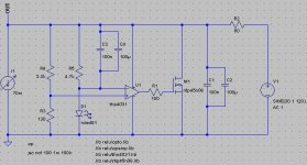
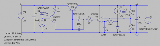
syn08 said:This is how I'm wiring this regulator. If the regulator is in the same case with the phono stage you may delete 3 and the shielded cable T1, and simply star the output/sense and the grounds/sense at the low noise input stage terminals.
I guarantee that using this schema will improve the performance.
Hi Syn, perhaps I'm missing something. My simulation of this circuit isn't doing very well. I do like its simplicity.
Attachments
Re: Re: Wiring
What is the problem?
ikoflexer said:
Hi Syn, perhaps I'm missing something. My simulation of this circuit isn't doing very well. I do like its simplicity.
What is the problem?
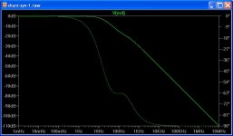
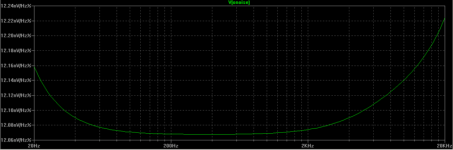
As long as we're simulating things, I thought I'd have a look at the improved Jung regulator. The output impedance is nice: below 1mOhm from DC to 4kHz, rising to 25mOhm at 96kHz.
An externally hosted image should be here but it was not working when we last tested it.
Attachments
onvinyl, nice result. Just in case, you might want to try inserting an LC filter just in front of the 22R resistor. I think you'll be surprised of the results. It does not matter how small the L and the C are.
salas, sure, I will post the result, although I'm not sure if people have any interest in that circuit.
Edit: here's the post where the result can be seen.
http://www.diyaudio.com/forums/showthread.php?postid=1738260#post1738260
salas, sure, I will post the result, although I'm not sure if people have any interest in that circuit.
Edit: here's the post where the result can be seen.
http://www.diyaudio.com/forums/showthread.php?postid=1738260#post1738260
Quote
Compare again The minnesota uses a pnp and the opamp is flipped.. Why is the minnesota decoupling the divider up to the output?
Unquote.
The reason to place a cap across th e top leg of th e divider is so that the noise on the shunt output line is directly couled to the feedback input to th e op-amp. If you do not do this, the error signal is divided by the feedback ration - so in effect you have much less loop gain available to correct th e error signal. (Assumption: the cap is a low value compared to the parrallel resistor value).
Try this on your sims to see th e improvement.
Of course, you still have to use a value that keeps your sustem stable.
Refering to the Minnesota shunt reg schematic
1. They are doing what I mentioned in my 1st post - th e bipolar pass element is running in follower mode - so the output pole problem you get with a commom collector config is greatly reduced
2. They are using bipolars because they are much cheaper than mosfets
salas, sorry, I was playing around simulating onvinyl's regulator, which looks very interesting, but something is a bit off about it. If people show interest in our version we can open a discussion on it.
jwb, I would have to agree with you on the Jung regulator. It was designed and built by a professional. I don't have many doubts that whatever versions we simulate here are not as good, in reality, when the parts hit the board.
onvinyl, I can simulate just fine with the lt1115. If you don't use the alternate solver in the Control panel of ltspice, I would recommend turning it on. You can also set
.options reltol=1e-7 nomarch plotwinsize=0
for better accuracy.
The Minnesota cct
1. uses a heavy 1000uF output decoupling cap - I also would use a big output cap because this means you can use a relatively slow, low noise op amp for the control element. This approach also makes it easier to use a slow bipolar pass element
2. C3 is the feedback 'coupling' cap I mention in my previous post - maximises the avaiable loop gain for error correction.
3. They have decoupled the reference quite heavily as I mentioned in my first post
- Status
- This old topic is closed. If you want to reopen this topic, contact a moderator using the "Report Post" button.
- Home
- Amplifiers
- Power Supplies
- Best low noise regulator?