janneman said:
The error amp works open loop.
Jan
Any comments on topologies where the error amp has a defined closed loop gain such as Manfred Huber's designs?
I wonder whether this really can be called open loop as it obviously closes through the power rail.
housing said:How about LT1027?
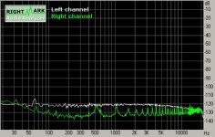
Looks good on paper, although the frequency response doesn't seem that great - unfortunately I don't have any. LT is not very generous with samples

analog_sa said:
Jan
Any comments on topologies where the error amp has a defined closed loop gain such as Manfred Huber's designs?
I wonder whether this really can be called open loop as it obviously closes through the power rail.
That's not a regulator, It's a DC amp that amplifies the ref voltage a number of times with a common source follower buffer.
Jan Didden
Post 10 looks like a regulator to me (with global feedback), a HV one at that. The nested loop around the OPA637 helps to control overshoot and ring to small signal deviations on the rail, but does so at a cost of overall line/load performance. It will also tend to flatten out the regulator’s impedance (ignoring the effects of the bypass cap), in the case of the OPA637, to a bit over a 1MHz. But it does so by bringing up the minimum impedance value. Looks like a pretty decent design for a tube supply (does a tube working at 350V really need all that??).
But what do I know, I don’t understand shunt regulators.
But what do I know, I don’t understand shunt regulators.
I remember times (late 90ies) when they would pamper us engineers with a box full of samples and ev-boards of their newest stuff almost every week. Even stuff I never requested! Now the cat got fat and lazy, it seems.syn08 said:LT is not very generous with samples
BTW, I also don't seem to understand the role of those caps accross the LED feed resistor. Is this an empirical thing only or something conceptual I'm missing?
- Klaus
kaos said:I’m sorry, I can’t see the regulator in post 21’s schematic working at all. The gain of the error amp is set by the feedback loop ratio of R4 & 5, which as pictured is around 26. The LED reference should be around a volt or so for that LED (looking at the data sheet), so that would yield an output voltage of around 26V. The input is only 15 volts in the schematic. What’s the output voltage supposed to be?? The addition of C1 & 2 across R5 is a positive feedback path and should lead to worse noise, if not outright instability. Perhaps C3 mitigates that to some degree (lag vs. lead)?? Sounds tricky at best. Commonly, despite the pictures, C1 & 2 would be across D1 (C1 would be made somewhat larger in that case), with a counter diode across R5 to protect U13’s input from the charge stored in C1 & 2 at power down. To reduce noise it’s common to place a cap across the feedback resistor, in this case R4, though stability issues need to be considered when that’s done. I’m at a loss as to how this regulator can be expected to work optimally as pictured. Am I missing something?? Sorry, don’t mean to come across harsh, just at a loss …
syn08 said:
Yes. You miss the understanding on how parallel regulators are working
Syn,
Unfortunately I didn't have time to follow the earlier thread where
your reg came up so apologies if you have already covered this.
There are some interesting but somewhat, at first glance, odd
arrangements in your reg.
Is it possible that you can explain a little more clearly how the
(effectively) OP driven LED works?
If this reg is re-drawn as a simple opamp circuit sans OP fet, with
the +/- IP's swapped it appears not optimal noise wise.
It would appear to me that the noise of R243 is multiplied by the
gain of that resistor string R242 & R243.
Thanks,
Terry
analog_sa said:Not a regulator?! Are you talking about the circuit in post #10? Yes, the amp is there but it amplifies the difference between the ref voltage and a fraction of the output. How can this not be a regulator?
You are right, it *is* a regulator. My bad.
I wonder why that design has the error amp limited in gain? One would expect that running it open loop would make for a much better regulator. Maybe he had stability issues he tried to fix by lowering the loop gain?
Jan Didden
kaos said:Post 10 looks like a regulator to me (with global feedback), a HV one at that. The nested loop around the OPA637 helps to control overshoot and ring to small signal deviations on the rail, but does so at a cost of overall line/load performance. It will also tend to flatten out the regulator’s impedance (ignoring the effects of the bypass cap), in the case of the OPA637, to a bit over a 1MHz. But it does so by bringing up the minimum impedance value. Looks like a pretty decent design for a tube supply (does a tube working at 350V really need all that??).
But what do I know, I don’t understand shunt regulators.
That maybe the reason for the limited loop gain (trying to minimize ringing/overshoot). But proper compensation should be used for that, and then getting the lowest possible output impedance and best PSRR. A flat impedance curve in itself is no virtue; I'd rather have a Zout of 100u Ohms at 1kHz rising to 10m Ohms at 1Meg than a flat one of 10m Ohms from 1k to 1Meg.
Jan Didden
These are all pretty standard shunt regulators, and I think its quite easy to get better than 80db of load rejection at 20kHz with a bit of effort. Whether or not you can consistently get down to below 100dB at 20KHz given the variables of layout etc is debatable. However, shunt regulators are an extremely useful tool, and op-amps along with FETS make ideal circuits (bipolar pass devices put a nasty pole in th e loop response, so you have to 'slug' the loop response - this leades to bad performance at higher frequencies, although you can mitigate against this a bit by configuring the circuit so the pass element is a follower).
A few points I noted reading through this thread.
1. Reference - noise in itself from the Vref should not be a problem - just use an RC to filter it before it goes into op-amp input reference pin. I guess 1/f noise is the main issue, but op-amps generally excel at PSRR in the sub 10Hz region.
2. LED's as a reference - nice and low noise to boot - but don't forget the -2.2mV temp co-eff. Good idea to stack 2 or 3 of them to raise the reference voltage.
3. The value and type of output cap (i.e. cap across the load) is a critical factor in performance. I ran some sims using the models in the LTSpice library and these include Ls and Rs and make a big difference compared to using a bog standard 'perfect' cap. My regulator performance went from -100dB at 20KHz to -80dB.
4. Op-amp. Make sure your op-amp inputs and output drive can handle the common mode input voltage (many high speed op-amps struggle with inputs within 1-1.5V of the rails. Similarly, use a mosfet with relatively high Vgs(th) to avoid problems where the op-amp output cannot swing low enough.
5. Test your regulator with a square wave load. Easy then to pick up any overshoot or ringing.
Hi Bonsai,
Yes, point 3) in particular is often misunderstood. In fact, you *want* a lossy cap for stability reasons - a standard electrolytic is fine. People often use very expensive boutique film caps here and then are surprised when it oscillates. This is one area where you can have your cake (low cost cap) and eat it too (stable reg)
Jan Didden
Excellent coverage Bonsai, I can't think right now of anything to add.
At point 4), though, this could be the reason why analog_sa was running in some issues (opamp motorboating). OPA627 has only +/-12.3V output swing, while IRF610 has a threshold of 2...4V. Certainly, there is a combination of OPA627 and IRF610 that would not work properly, and God knows what's happening when the output swing border condition is encountered. THS4031 I am using swings to +/-13.6V that covers even the worst case (including temperature effects).
At point 4), though, this could be the reason why analog_sa was running in some issues (opamp motorboating). OPA627 has only +/-12.3V output swing, while IRF610 has a threshold of 2...4V. Certainly, there is a combination of OPA627 and IRF610 that would not work properly, and God knows what's happening when the output swing border condition is encountered. THS4031 I am using swings to +/-13.6V that covers even the worst case (including temperature effects).
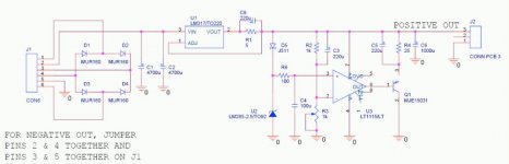
Because they use a BJT, they must also use R5 and C5 to avoid problems with the output voltage of the opamp.
Your suggestion that anybody who uses a MOSFET doesn't know what they do is just as wrong as suggesting that anybody who uses a BJT doesn't know what they do. The fact that you don't know why someone does something doesn't mean there isn't a good reason for it.
There are many roads that lead to Rome.
Jan Didden
KSTR said:Relax, Jan,
you seem to have read Dodo wrong, in a hurry (double negation can be tricky
- Klaus
But Klaus, I am relaxed
I just wanted to indicate that there may be reasons for one or the other we are not aware of. I once used a particular transistor because I had 200 left from another project...
I had no intention to insult Dodo, if it looks like that I apologize.
Jan Didden
Guys, I agree that this little regulator is actually more complex than it appears at the first glance. There are literally hundreds of combinations you can build this, and here are a few variables I can quickly think of:
- Bipolar/MOSFET
- Polarity (NPN/PNP or Nchannel/Pchannel, with flipping the opamp inputs)
- Reference type
- Current source to feed the reference (yes, using a resistor to the output or a CCS like a JFET makes a significant difference)
- Ballast resistor or CCS
- Output cap value and ESR+ESL
- Reference bypassing cap value
- Reference bypassing connection (ground/output, yes it makes a very significant difference)
- Other bypassing (control input, like in the Minnesota shunt, yes, it makes a very significant difference).
If somebody with a simulator and enough time could try to optimize and find the best combination of the above, I would be the first to appreciate the effort.
Given the limited time I have, my intention was only to show something that works very good for me (actually probably as good or better than any discrete parallel regulator I can think of, at a fraction of complexity, size and cost).
- Status
- This old topic is closed. If you want to reopen this topic, contact a moderator using the "Report Post" button.
- Home
- Amplifiers
- Power Supplies
- Best low noise regulator?