Thanks Kean, great you are here
that its possible to make it do what I want is all I need to know...for now
the work continues
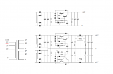
glad you like my drawing
I do it to make it more 'compact', in the first place
and in the process I try to make it easier for myself to 'understand'
its like when its 'easy on your eyes', its also gets easier to 'read it'
may sound weird, but its kind of like a balance between empty space and components
often I try 3 or 4 different variations of various connections, sometimes more
may seem a bit stupid, and waste of time
but at the of the day I know every single component
I dont know the function of each component, but I will know where it should be mounted
that its possible to make it do what I want is all I need to know...for now
the work continues
glad you like my drawing
I do it to make it more 'compact', in the first place
and in the process I try to make it easier for myself to 'understand'
its like when its 'easy on your eyes', its also gets easier to 'read it'
may sound weird, but its kind of like a balance between empty space and components
often I try 3 or 4 different variations of various connections, sometimes more
may seem a bit stupid, and waste of time
but at the of the day I know every single component
I dont know the function of each component, but I will know where it should be mounted
I always try to use neat but compact schematics in the simulator. Compact because it has to share half the screen with the waveform viewer. So most of my schematics have a "widescreen" form factor. I think there should be a way to dimension the most common schematic symbols so they will naturally come together gracefully. I think LTSpice has struck a reasonable balance on this.
Use the schematic in the webpage. It is much newer, and less likely to fail.
I would still put snubbers on the input and output, and this applies for any regulator really.
ok chief
Attachments
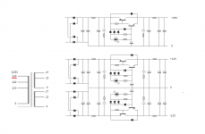

You can replace the top two diodes with a 3.3k resistor, and add a 12V zener + diode from the 3rd diode anode to ground. Then you will have 12V output without any extra transistors.
But then the circuit will be limited to 130mA max at 2W dissipation. The output transistor will need a heatsink if you need more.
However, the Kmultiplier isn't better than the chipregs in all ways. It is faster and has more PSRR above 10KHz, less output impedance at 100KHz. But at 120Hz it will have less PSRR. The Kmultiplier is intended for applications that don't require a regulator but that can still benefit from a low-impedance rail.
But at 120Hz it will have less PSRR.
ah, ok
I need to think about this once more
thanks Kean !
However, the Kmultiplier isn't better than the chipregs in all ways.
ok, the weird, one of each
now, the question, will they work well together, or against each other
could be done as small seperate modules with small print connectors
that way it would be easy to make changes
Attachments
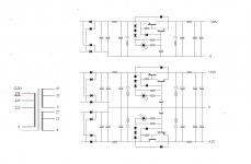
As far as putting the Kmultiplier before or after, you'll have to tell me which is better. You'll get lots of PSRR either way. The rest is a question of output impedance and transient behavior I think. I'm guessing that you're not worrying about output impedance because you have an RC at the output.
I'm guessing that you're not worrying about output impedance because you have an RC at the output.
not sure when low impedance power supply is 'needed'
I thought low impedance was mainly for high current power amps
but I guess also for wide bandwidth
but this is for a bass guitar preamp project
gain stages are often 'simple' designs, and PSRR is probably next to nothing
so, 'the best' power supply could still have positive influence
btw, I thought the series resistors would help protecting the regulator in the power on situation...like a simple softstart
the LED/bleeder I use now also seem to come on quite slowly, as does the voltage on the reg
As far as putting the Kmultiplier before or after, you'll have to tell me which is better.
I was mostly thinking of the 'sensitive' output of the IC regs, and thus chose it to drive the Kmultiplier
btw, each single gain stage(or buffer) will all still have their own lytic supply caps
something like a NIC nrsg type 35V/1000uf(ø12x25mm) will still only be 18mohm(0.018)
but I suppose less will do
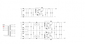
The Kmultiplier has lower Zout from the treble to several MHz, but below that the chipreg has lower Zout (at least at the currents it was tested in the datasheet). While the chipreg has higher internal feedback, it is also heavily compensated, and may have intermodulation problems with RFI. So it may be best to use the Kmultiplier first to block RFI.
For any audio circuit I would try filtering the PSU to remove RFI and EMI. Zout maybe does not need to be so low. I think the things responsible for sonic improvement from the Kmultipliers are a low bass output impedance, and good PSRR through the ultrasonics to several MHz.
A chipreg will limit inrush current to 1.5A which is no problem. The Kmultiplier also limits inrush, and you can alter this based on the Design Considerations section in my article. So the real danger is of having too much capacitance right after the rectifier, since the regulator limits inrush.
So it may be best to use the Kmultiplier first to block RFI.
For any audio circuit I would try filtering the PSU to remove RFI and EMI.

A chipreg will limit inrush current to 1.5A which is no problem. The Kmultiplier also limits inrush, and you can alter this based on the Design Considerations section in my article.
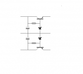
I just ran out a bode plot of the damper -- in comparison with a light resistive load of 13.8mA (1K) on a Jung "improved" regulator, the parallel value of 1K//390R and the damper illustrated in your post -- seems that the effect is pretty slight with the value of the damper primarily arising from the increased load, or decreased output impedance.Here is a nifty way to snub rails. Maybe you could call it the Ksnubber or Kdamper. Maybe I like the letter K too much.
An externally hosted image should be here but it was not working when we last tested it.
I'm not sure what you are doing. Do you mean you added the damper, then replaced it with a resistor, and then compared the two?
The damper circuit is for places where it's needed. The only reason I made it is because it's hard to find non-inductive variable resistors that go to 500mR! If I could see the Jung regulator output impedance+phase to 40MHz I could tell whether it would benefit from a snubber.
High-performance amp circuits that have a high UG point can have problems with resonating rails because the very low PSRR at these frequencies causes the rail impedance to become part of the OLG curve, 10MHz spikes and all. In this case local decoupling is the only answer, and sometimes you need a snubber to keep the decoupling from resonating through the rails. I had this problem recently.
The diode circuit allows us to experiment with rail snubbing with resistances that would ordinarily be very inconvenient and time consuming.
- Status
- This old topic is closed. If you want to reopen this topic, contact a moderator using the "Report Post" button.
- Home
- Amplifiers
- Power Supplies
- Best low noise regulator?