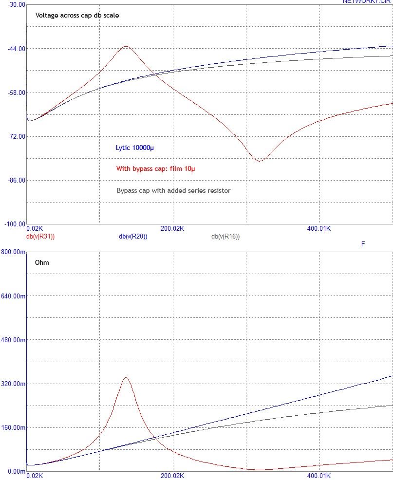
Bypass cap series resistors avoid dips and peaks im the impedance curve.
Things can be much improved by multiple different sized bypass caps,
and again with series resistors.
It can be seen that a single 10µ film cap worsens impedance up to 135 kHz before it gives an improvement at higher frequencies.
A single 1µ film cap worsens impedance up to 580 kHz, see earlier picture from analyzer.
Last edited:
Which values orders?
0,39 ohm for a 10µ MKP.
Evaluated with main cap 10000µ / 0,022 ohm ESR.
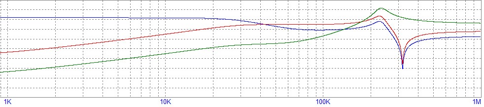
The picture below shows the impedance of 3 x 10.000 µF and the same 3 x 10.000 µF with 1µF MKV bypass.. . .
Very interesting info with that series resistor. I'm curious to see how that works out when you put a lot of gain on it. So here's a real life example.
Can you measure the difference between these two things?:
For both capacitor examples, they block dc from amplification within this negative feedback divider, 120k versus 2.7k.
1): 220uF//22uF//0.47uF
2): (220uF+3.3R)//22uF//0.47uF
These are both a 242.47uF NFB cap (which is in series with the 2.7k resistor that's hooked to the inverting input of an amplifier, as expected). In the example, that 3.3R has one end hooked to signal ground, lifting only the 220uF cap.
Option #2 sounds better, but why would that be?
I admire these works.All of them are useful.I want to learn that a mkt cap can sound better than mkp ones.Some people say that green ero mkt capacitors (they are mkt series like mkt1813) sounds better than blue ero mkp ones.Is it true?I know that mkt ones are very good for PS applications but i did not know that they are better in signal path.
I admire these works. All of them are useful. I want to learn that a mkt cap can sound better than mkp ones. Some people say that green ero mkt capacitors (they are mkt series like mkt1813) sounds better than blue ero mkp ones. Is it true? I know that mkt ones are very good for PS applications but i did not know that they are better in signal path.
This may vary mostly on whether high or low ESR is desired and whether you add or subtract series resistance, which then forms or omits a filter as well as increasing or decreasing voltage versus current drive effects. Therein, midrange and treble will decrease or increase, also providing much variety in harmonics.
Well, there's not a best capacitor for every signal path application, but rather that the idea of "best" varies per each individual application.
Also, a variance within a given application, especially a power circuit change/upgrade, will happen to cause a variance as to "best" selection of signal path capacitor(s) as well. So, please attempt to optimize power circuit before selecting "best" signal caps. That might save you from a re-do.
Yes, some minor cancellation on error is possible as is doubling up of error. Signal path capacitor choices can do that and more, but all variances from decent choices will be mild variances. So, there's no need to go either slow or expensive. If reasonable care won't do the job, then you're working on a spot where the problem isn't, and of course, efforts would be more productive if you worked on a spot that has a problem instead.
Simplified speedy selection method:
Take five "most likely capacitor samples" (could be your own favorites or data gathered from working examples or recommended samples) that are also the correct values and enough voltage tolerance. . . compare all five within a given application. . . and then, of course, install the one that sounded nicest.
Note that price doesn't determine performance--you determine performance.
Note that its more reliable (more flexible) to install a headphone jack and use headphones during this selection process, so that room variances don't influence your decisions.
Very interesting info with that series resistor. I'm curious to see how that works out when you put a lot of gain on it. So here's a real life example.
Can you measure the difference between these two things?:
For both capacitor examples, they block dc from amplification within this negative feedback divider, 120k versus 2.7k.
1): 220uF//22uF//0.47uF
2): (220uF+3.3R)//22uF//0.47uF
These are both a 242.47uF NFB cap (which is in series with the 2.7k resistor that's hooked to the inverting input of an amplifier, as expected). In the example, that 3.3R has one end hooked to signal ground, lifting only the 220uF cap.
Option #2 sounds better, but why would that be?
What you do is quite the opposite, to add a series resistor to the larger cap in a high impedance environment.
My interest is mostly power supply and maybe speaker dividing network, both 2 - 8 ohm load.
I'm just starting. My intention is a 68000µ ( or multiple ) psu cap with flat impedance to 1 MHz.
Preliminary recommendation for a single 68000µ cap: 2 x slim 1000µ lytic + 3 x [ 100µ film cap + 0,1 ohm ]
I admire these works.All of them are useful.I want to learn that a mkt cap can sound better than mkp ones.Some people say that green ero mkt capacitors (they are mkt series like mkt1813) sounds better than blue ero mkp ones.Is it true?I know that mkt ones are very good for PS applications but i did not know that they are better in signal path.
To correct my own
Also a bypass cap in a power amp supply should be MKP.
0,5 ohm is not very good in driving 4 ohm.
MKT as PSU bypass may be better than MKP,
if it has the right ESR value in relation to it's own C value.
In this case, MKT with internal ESR would behave the same like MKP with external series resistor.
For coupling caps I would prefer MKP. ( same type and value to prevent interaction )
This is what happens in a chain like: signal source - cap array - low impedance load, which we have in situations like: PSU - Amplifier - speaker and Amplifier - speaker dividing network - speaker.
The curves add up to a straight line.
Bypass with series resistor.
The curves add up to a straight line.
Bypass with series resistor.
Last edited:
anyone else noticed that new 105gr power supply caps have lower ripple current for the same size
or is it just a "spec trick" to get the higher heat ratings
how much do "they" fiddle back and forth with the specs
like say, a 10-15V difference seems to mostly influence capacitance
what difference is there really, inside the cap, to make a 10V difference
can is often the same size
hard to believe they change construction for a mere 10V difference
is it only a matter of different calculation
mind you, this only concerns caps of same can size, and with smaller spec differences
This is what happens in a chain like: signal source - cap array - low impedance load, which we have in situations like: PSU - Amplifier - speaker and Amplifier - speaker dividing network - speaker.
The curves add up to a straight line.
Bypass with series resistor.
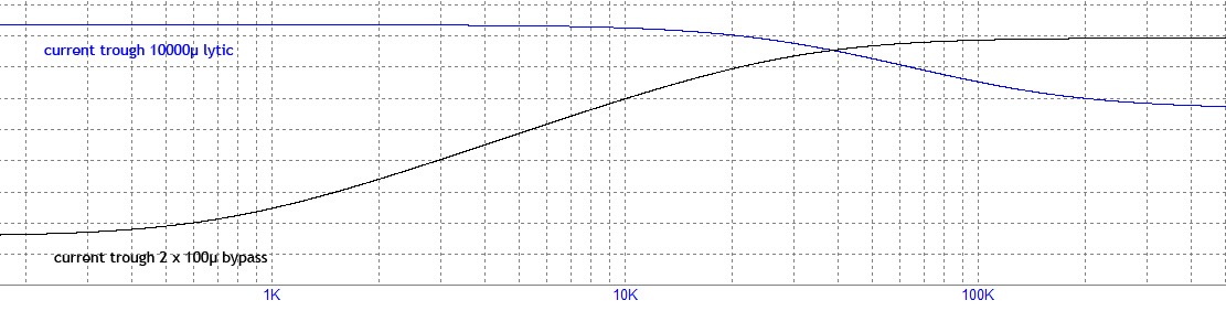
Woah! That response is drooping right after the ear's sensitivity peak. This is most annoying! Even a small error in the wrong direction will be very noticeable. The big caps need corrected so they can reach 22khz with a flat response.
Same for 10000µ + 100µ + 10µ but NO series resistors.
Blue is current through lytic, red 100µ bypass, green 10µ bypass.
IMHO for a PSU we must consider:
1) Because the cap acts as high pass for the load, a lytic must be as large as possible to have lowest impedance at low frequencies.
Perhaps lots of smaller lytics paralleled could bring improvement by lowering ESR and could make the task of bypass caps easier by lowering series inductance.
2) Because the lytic cap's series inductance acts as low pass for the load, the amplifier can not work properly at high frequencies.
A compensation is needed.
HQ film caps have low series inductance and can jump in.
The value of the film cap must be large enough so that there is no gap between the lytic and the bypass.
If it is too large, there will be overlap.
So the bypass must have a specific value that depends on the C value and parasitics of the main cap.
3) Parallel connection of lytic + bypass causes dips and peaks in the impedance curve which must be dampened by series resistors added to the bypass.
There is no general solution like 2µ MPK and 100n silver mica sounds good as bypass...
Disclaimer: IMHO
Last edited:
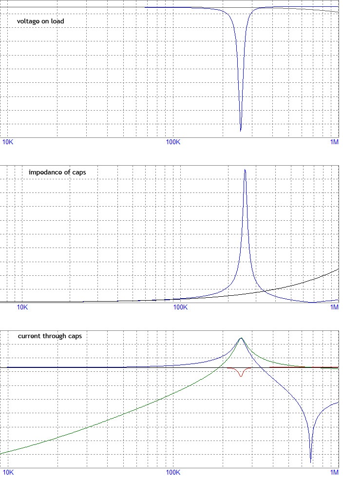
Here is what you find in a good amplifier: 22000µ + 2,2µ bypass and no series resistor.
First graph:
-6 dB dip on the load @ 250 kHz. The rest looks very good.
Without bypass there would be only -0,3 dB @ 1MHz, no cable inductances taken into account....
Second graph:
PSU impedance raises to 3,8 ohm @ 250 kHz.
0,22 ohm without bypass @ 250 kHz.
Third graph:
With bypass:
Blue is current trough main cap.
Green bypass.
Red load.
It looks like main cap and bypass cap are resonating.
By adding a series resistor to the bypass cap, that resonance is stopped.
Without bypass:
Black is current through load.
----------------------------------------------------------
Because the impedance values of the caps are very low even at 1 MHz and the voltage loss depends on the load, the impact is very small in numbers.
But as most people believe there is an audible difference, it must matter.
Maybe a power amplifier like opamps and digital ICs needs perfect decoupling far above it's bandwith to provide stability and differences could be seen on squarewaves.
But it also could be that if the amp bandwith is 100 kHz and the dip / resonance is @ 250 kHz,
everything is already perfect and no need for series resistors.
Woah! That response is drooping right after the ear's sensitivity peak. This is most annoying! Even a small error in the wrong direction will be very noticeable. The big caps need corrected so they can reach 22khz with a flat response.
This is only because the bypass cap takes over.
On a single large lytic it would be flat to 100 kHz.
Still, differences with and without different bypass caps seem to be audible...
This is only because the bypass cap takes over.
On a single large lytic it would be flat to 100 kHz.
Still, differences with and without different bypass caps seem to be audible...
Oh, I only meant that maybe the bypass could start boosting at 8k instead of waiting until. . . beyond the audio band.
interesting reading
http://docs-europe.electrocomponents.com/webdocs/0081/0900766b800813e4.pdf
one quote, about cooling
In order to lower the thermal resistance between winding and case, can-type capacitors produced
by EPCOS have a thermal bridge between the capacitor winding and the base. As a large amount
of heat is dissipated through the base of the case, the use of a heat sink connected to the capacitor
base is the most efficient cooling method. For this reason some capacitor types are fitted with a
threaded stud for mounting them on a heat sink.
- Home
- Design & Build
- Parts
- Best electrolytic capacitors