Film types is ok if they are without the "M". KP and polystyrene types are good but MKP and MKT types make the treble live its own life separeated from the rest.Hi Erlend Sæterdal,
Do you mean that electrolytic capacitors sound better than MKP capacitors?
Film types is ok if they are without the "M". KP and polystyrene types are good but MKP and MKT types make the treble live its own life separeated from the rest.
In My Opinion and that of several analog amp chip makers, the best of both worlds, electrolytic and plastic, is to use both. Use the larger electrolytic caps to do the heavy lifting filtering (large capacitance, several dozen micro-Farads, on the +v/0/-v rails) and parallel these with plastic caps (MKP & MKT types are good for this).
Results may appear subjective, but there is ample evidence that paralleling plastic caps across the power pins of op-amps does improve performance and noise rejection ... at least for low level signal to power supply noise rejection.
On my power amps, I will always add good sized 1 mF plastic caps right across the connectors on the big 100+ mF electro-honkers. The subjective results seem to be improvements in electrolytic capacitor "fatigue" (perceived improvements long term), after warm up and extended usage ... keeping the high end quite "lively" into the wee hours
 .
.
Last edited:
... See >> http://www.diyaudio.com/forums/soli...ur-solid-state-pics-here-116.html#post1973380 Shortly after these pics were taken, I added two MKT plastic 2 uF caps across the connectors of the big blue boys in the back (+62vdc / 0 / -62vdc) ... proved to "cure" the fatigue factor, IMOP. ... Several hundred hours of play time later = no apparent "fatigue factor" and still runs very cool, no fan. ... drives those big Magnapans nicely.
Right hand picture shows almost hidden sub woofer (center right under cookie jar / table) ... now driven with single channel amp with the same treatment: plastic caps paralleled across the electrolytics. (I'll be bringing this sub woofer amp to the Burning Amp Fest in San Francisco 10/30/2010.)
Last edited:
Looks great ! I have done the NXV 300 and to sets of NXV 500. The Magnepans and all those plastic cables explain me why you can not hear what I am talking about.
What means fatigue ? I am Danish 55 years and do not remember all my school English.
My whole system is with Solidcore and Plasticfree.
What means fatigue ? I am Danish 55 years and do not remember all my school English.
My whole system is with Solidcore and Plasticfree.
... explain me why you can not hear what I am talking about. ... What means fatigue ? ...
Not only that, I'm 66 years old and my ears are not as good as when I built equipment for performance venues & dance halls.
What is capacitor fatigue?
A phenomena associated with (usually) electrolytic capacitors where, after a time, the capacitor losses its ability to respond (replenish the DC power) ... Somewhat.
If the capacitors of an audio system are not "oversized", but "engineered" to be "just enough to do the job", this fatigue phenomena may easily happen ... with the noise floor diminishing over extended listen sessions to the point of power supply noise becoming audible.
Cure #1: Use "oversized" electrolytic capacitors ... size your capacitor value to 150+% or more of calculated requirements. It is common practice among us DIYers to over do this, using massively oversized electrolytic caps in any case!
Cure #2: Add plastic capacitors in parallel with the electrolytics. Plastic caps do respond faster than electrolytics = faster rise times.
My cure #3: Do both.

I regularly add plastic caps to any "store bought" audio equipment, just to be sure. (Example might be the Oppodigital.com DVD players, in which I have added two 1.0 mF yellow MKT type caps at the power supply connector on the audio boards = with noticeably better results.)
References: See http://focus.ti.com/lit/ds/symlink/ucc3809.pdf ... Note the circuit diagram on page 4 ... Note the several additional paralleled filter caps close coupled to UCC3809 IC = one of these is a plastic cap for good reason. The device circuit can become unstable without it, because of fatigue developing in the associated electrolytic power supply caps! (This design has at least 6 paralleled PS caps plus active voltage regulation ... and would probably fail, long term, without the added plastic caps.)
Last edited:
I would prefer for power supplies the MKT1813Hi.We know that Ero kp capacitors sounds very well(they are not metallized ones).I want to ask a question.Ero mkt1813 or Ero kp1832.Which one is better for using in power supplies ?Thanks
http://www.vishay.com/docs/26013/mkt1813.pdf
alternatives:
http://www.wima.de/EN/mks2.htm
http://www.wima.de/EN/mks4.htm
The KP1832 (no longer available, now KP1830/1836) I would prefer for frequency dependend applications e. g. for active crossover devices, equalizer, baxandall-equalizer and couple caps in tube amps
http://www.vishay.com/docs/26016/kp1830.pdf
http://www.vishay.com/docs/26021/kp1836.pdf
alternative: http://www.wima.de/EN/fkp1.htm
http://www.diyaudio.com/forums/swap-meet/162216-ero-kp1832-capacitors-better-than-mkp-caps.html
Please note, the max available capacity value is much more lower by KP than MKT/MKP.
For passive networks this caps are very good:
http://www.wima.de/EN/dclinkmkp4.htm
Last edited:
An engineer from Nichicon now works for Chinsan and makes the delightful Chinsan Elite SD capacitors.
I've routinely used them for NFB caps (!!!), and for power supply caps at the amplifier board and preamp board.
I've experience with the 220uF, 100uF, 10uF, 4.7uF and 1uF 50V Elite SD and those have "won in a competition of peers" that included Elna Cerafine and Nichicon Muse series.
The effect on a presentation was simple and clean--really very clean with an unusually wide bandwidth for flatter frequency response. I'd suggest these Elite SD to people who are using modeling software and want expected results.
An engineer from Nichicon now works for Chinsan and makes the delightful Chinsan Elite SD capacitors.
Elite - High Quality Aluminum Capacitors (supported by Chinsan Electronic)
I cannot see the ELite SD anywhere on their site...
ESR in ohm measured with Philips RLC meter @ 1kHz.
0 means < 0,01 ohm.
it shows that larger uF values and higher voltages have lower ESR.
Paralleling caps results in lower ESR like does paralleling resistors.
Two 0,05 ohm caps give 0,025 ohm.
MKT bypass is worse than large lytic, at least at 1 kHz.
Nichicon Muse 0,47u 50V = 20, I don't think it is dried out, capacitance is ok and I tested a few samples.
Green drop MKT ? 0,1u = 6
Small lytics and MKTs can reach up to 10 ohms.
Tantal also does not look good.
Tektronix = 0
KP = 0
KS= 0
MKP = 0
MKY = 0
TRW = 0
MKV = 0
Silver Mica = 0
Teflon =
MKC =
Wima MKS4 15u 100V = 0,05
MKL 2,2u 63V = 1,2
MKT 2,2u 250V = 0,34
MKT-S 10u 100V = 0,05
MKL 10u = 0,3
MKL 47u 100V = 0,06
MKT-S 47u 100V = 0,02
MKT 6,8u 100V = 0,1
Tantal mil = 0,22
tantal roe = 0,25
Blitzelko 880u 330V = 0,06
Elko glatt = 0,07
Oscon 220u 10V = 0,06
BG 2200u 16V = 0,03
BG 1000u 6V = 0,04
BG 1000u 25V = 0,024
BG 220u 16V = 0,07
BG 220u 6V = 0,23
BG 470u 35V = 0,028
BG 470u 16V = 0,036
BG 22u 25V = 0,3
BG 10u 25V = 1,1
Motherboard 1500u 16V = 0,017
Motherboard 1500u 10V = 0,02
Last edited:
Green drop MKT (?) 0,1u = 6, for comparison: KS 0,047u = 0
Because speakers have impedance down to < 4 ohm, it is not a good idea to use MKT in speaker crossover networks because of loss.
Upgrading existing networks from MKT to MKP may require adjustment of resistive attenuator, a tweeter could become louder otherwise.
Also a bypass cap in a power amp supply should be MKP.
0,5 ohm is not very good in driving 4 ohm.
MKL 110u 630V = 0,02
Nippon Chemicon 33000u 10V = 0,006
Last edited:
Deciding to investigate these ideas of capacitor quality further, I ran across this old (lengthy) article in Electronic Design Magazine: "What's all this soakage stuff, anyhow?" - by Bob Pease / May 13, 1998
" ... in the IRE Transactions on Electronic Computers (analog computers, in those days, of course), March 1958, pp. 17-22, measured the soakage of the best capacitors of the day—polystyrene. ..."
The complicated issue: This "soakage" is directly related cap induced phase shifting, leakage, impedance imbalances v. frequency and a raft of other capacitor characteristics that relate to capacitor quality for our audio purposes here.
---
FYI: coming soon to a surplus store near you: multi Farad carbon capacitors! " Paper-thin supercapacitor has higher capacitance when twisted than any non-twisted supercapacitor " - Sept. 21, 2010 By Lisa Zyga at Physorg.com ... Holy Cow: " ... the new supercapacitor has a capacitance of 31.4 F/g when twisted, compared to 5.2 F/g for current commercial supercapacitors ..."
Imaging a power supply bypass capacitor of 30 Farads ... :  ... And its smaller than a cell phone ...
" ... in the IRE Transactions on Electronic Computers (analog computers, in those days, of course), March 1958, pp. 17-22, measured the soakage of the best capacitors of the day—polystyrene. ..."
The complicated issue: This "soakage" is directly related cap induced phase shifting, leakage, impedance imbalances v. frequency and a raft of other capacitor characteristics that relate to capacitor quality for our audio purposes here.
---
FYI: coming soon to a surplus store near you: multi Farad carbon capacitors! " Paper-thin supercapacitor has higher capacitance when twisted than any non-twisted supercapacitor " - Sept. 21, 2010 By Lisa Zyga at Physorg.com ... Holy Cow: " ... the new supercapacitor has a capacitance of 31.4 F/g when twisted, compared to 5.2 F/g for current commercial supercapacitors ..."
Imaging a power supply bypass capacitor of 30 Farads ...
: ... And its smaller than a cell phone ...
Last edited:
Elite - High Quality Aluminum Capacitors (supported by Chinsan Electronic)
I cannot see the ELite SD anywhere on their site...
Elite PS is the same product.
http://chinsan.co.th/files/PS.pdf
It is unfortunately difficult to make a purchase from Chinsan, and I don't know of a reliable vendor.
I'd like a bucket of each of these:
PS 220uF 50v
PS 100uF 50v
PS 10uF 50v
PS 1uF 50v
SM 10,000uF 25v + 4,700uF 25v (most useful together)
I don't particularly need their 0.5uF, 1uF because Nichicon ES can do that job, and for 4.7uF Elna new Cerafine can do that job. However, I really do need the rest of the list because they're as flawless as a capacitor gets and they "plug n play" into modeled designs, giving expected results. . . in hi-fi.
Given my positive experiences I now use solid polymer caps wherever possible. You need to be aware of the very low ESR (don't put them directly after regulators etc.) but often these issues aren't relevant.
See Nichicon's current range: Conductive Polymer Aluminum Solid Electrolytic Capacitors
Solid polymer caps typically have better lifespan, ripple current rating, lower ESR etc. than the most luxurious audiophile electrolytics. Not right for all applications, but absolutely the best choice for many applications.
Try them as a cathode bypass cap - you'll never live with Silmic or any other electrolytic in this position again ;-)
Preamplifier bypass or output bypass?
I am wondering which would be more critical to fidelity, cathode bypass of the preamp tube or the output tube in a single ended 2A3 amp. Any opinions? (I have only one pair of Black gates I can use) I am new here so I hope I am not misplacing this question.
Thanks,
Specimen
I am wondering which would be more critical to fidelity, cathode bypass of the preamp tube or the output tube in a single ended 2A3 amp. Any opinions? (I have only one pair of Black gates I can use) I am new here so I hope I am not misplacing this question.
Thanks,
Specimen
Where is the impedance minimum of a cap
in the 22000uF range ?
Any links to datasheets ?
0.03 ohms, according to the capacitor tester's front panel chart.
Such large value caps should have very little resistance to a signal. In this case, you'd probably like put additional 2200uF ~ 4700uF (in that range) cap directly at the rectifier, to help with the smoothing job.
Just remember that when adding in 'bypass caps' or crossing a film cap across an electrolytic to 'speed it up' we are creating a resonant coupling situation, akin to the no-no of placing two different woofers in the same pressure loaded chamber. You are going to get an unwanted resonance in such wide band situations, it really is that simple. Some bits of the high frequency response will be cleaned up but the whole idea is to deal with near RF delta's or transients in a better way..and THAT is the part that gets messed up, even though at first impression it does sound smoother and cleaner.
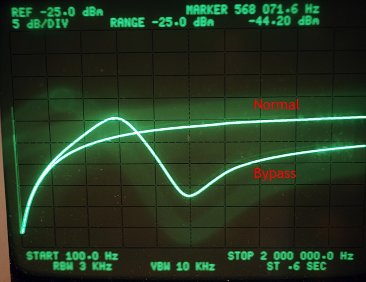
The picture below shows the impedance of 3 x 10.000 µF and the same 3 x 10.000 µF with 1µF MKV bypass.
I soldered two BNC cables to a split ground plane that holds the lytics and added the film cap.
BNC cables go to tracking generator 50 ohm output and Analyzer input.
That means, the caps shunt the signal to gnd.
Is this a correct setup ?
Last edited:
- Home
- Design & Build
- Parts
- Best electrolytic capacitors