Now that looks way more accurate and genuine
") I hope they change the picture on their catalogue, otherwize it might get confusing.
I hope they change the picture on their catalogue, otherwize it might get confusing.Actually it is the only "good" value.
What does the 30W mean??
Certainly this transformer does not do 30W secondary power.
Does it mean the power tube can be operated with 30W of anode dissipation (more likely)?
By the way, with let's say 400 Vpk-pk at the anode, the secondary power at 8 ohm is less than 6W.
Monolith specifies core saturation treshold with respect to frequency and power, which is the correct way; the Onori 18H @50hz is useless info.
Power output seems a bit vague among transformer manufacturers.
Usually it should be the translated to the maximum power output at specific distortion level for specific output stages at a specific lowest frequency.
It is much easier however to quote maximum power at lowest frequency for a specific maximum flux density value. Which should be quoted within the datasheets. Lundahl for example, quote their stuff in terms of flux density distribution, having determined a 1.6T saturation point for GOSS with an approximate 50%50% Bac to Bdc ratio (0.8T + 0.8T).
I quote my stuff at 1.4T for GOSS and 0.9-1T 25Hz for nanocrystalline/amorphous, because this is where the saturation knee often begins for all these three materials.
Sorry for use this example given by Andy...Here's another one. Noguchi are a shop and also make their own apparently good OPTs
???NO.1 ??3.000??????:, ?????????????
F-912 シングル出力トランス
• Pri :2.5kΩ
• Sec : 4-8-16Ω
• Frequency Range : 20~95kHz
• Output : 8w
• Pri Max DC Current : 70mA
• Pri inductance : 16H
• Dimensions : 102x90(max101)x115
Price is about £125 each
But this is classic example of really inapropriate and BAD OT for the 300B tube.
The KEY FACTOR in SE OT design is inductance of primary coil.
These 16Hy IS a way to be wrongly inssuficiant, and that could be easely shecked with simulations.
And there also results will be much worse in -db@bass AND phase shift too!!!
That 16Hy is low for the 2A3 tube with muxh lower internal resistance than 300B...
At 20Hz this OT probably will have more than -45% deg. Thera are no use to write -db value without phase data...
.
The ored of factor importance is the next:
1. First thing fr OT You should check Lp inductance and it should be not less than 40Hy. IF the inductance is low the working elipse (not ststic load line) is turning into circle. With increasing input signal aproaching max tube power, these elipse is "distorted and clashing into the X axis represents a Voltage value. (Y axes is Current)
Making the absence of LF and increasing phase shift in the same time as inkreasing the distortion in the LF region. So that is strongly limits max clean power of the device that will not be 8W or 10W, but 2-3W of undistorted power...
.
2. second thing is to get the information about the air GAP to compare with Lc.
.
3. to check about relative permeability of hte iron core laminations. Optimum is about the 800 of relative permaebility. That keeping the ratio of lenght of magnetic lines in laminations and air gap in optimal ratio. An reducing the chance of core going to saturation... That is in strong correlation with GAP and posibile saturation of the core...
In these terms high permability cores ARE NOT good for use in the OT transformer design. LIke nano or similar...
.
4. If You have the chance check the nuber of turns in the primary, because from that and from max level input and thus max voltage trough primary, You can calculate induction in [T] of the primary. That should be max to 1.4 [T] for the choosen Fo. but preferably less than 1 [T]
.
5. Next thing is to have infprmation of Rdc of the pimarry and most important secondary layer. As the secondary layer have less Rdc as Damping factor of the amp will be higher. Also Rdc of primary should remaim reasonably small...
In these factor is recommended that cross section of the core should remain square. Nit the huge paralelogram as we frequently see... The lenght of just one core turn is increased 2 x diff. from shorter to longer side of the core.
Multiply with say 3000 turns and diference of 1cm a-b, that is 3000x2cm=6000cm, with corresponding Rdc value...
.
6. Check and measure Cpacitance, Ls of the OT for have picture what is happenong at HIGH F... That should be as good as in the bass to have some meaning. So BW and Phase shift in LF and HF chould be cloe to each other...
for this estimation it is good to have number of sections combined secondary. For inrreased nuber of sections, the Ls will be smaller and capacitance will be smaller too... So it is better to obtain OT with 5-6 sections than one eith 2-3...
.
7. Last thing is static ratio of the transformer - that means ONLY the transformation ratio in fictional non-dynamic regieme...
.
There are more factors but these 7 are most crucial in this order.
...
You have been noticed that most of the key factor datas are not given. Anyhow. Also very rare BW measurements of transfer with a phase are missing from the reports...
.
cheers
Last edited:
These are "abstract" graphs measured as said, with generator in addition of 700ohm resistor to emulate real tube source.
These are not real circuit measurements. As the transfer is affected by other components values like pS C @ anode, Ck bypass etc.
But they didnt said what level of signal?
And of course shoul de be measured with huge signal, because signal i amplifiwed by the tube, and at grid is alreday about 40V p-p for max power. So it should be measured with more than 200V to emulate more real opperation.
.
They are probably measured vith fwe volts - that is mean not much
6. ..............
for this estimation it is good to have number of sections combined secondary. For inrreased nuber of sections, the Ls will be smaller and capacitance will be smaller too... So it is better to obtain OT with 5-6 sections than one eith 2-3...
Definitely no. Capacitance always increases with the number of interleaves.
to Zoran,
I am agree but, for me, the measurement with a linear load is the best way to understand how good is the trafo. I mean a resistor load connected to primary and secondary.
Also, in my opinion, the backward test is much better because you can get a great swing on primary that is not possible to get with a good generator
If you use the real circuit the non linear devices are involved in addition to the OT ( that it is also not linear, of course)
Walter
this are
Etude 1
for price ask you by mail
RS-3 is value for money transformer that replaces the oldThanks merlin.
@nicoch58
I dont find that transformer
Etude 1
for price ask you by mail
That is not true because the layer are more tin so the totla capacitance of one section is higherDefinitely no. Capacitance always increases with the number of interleaves.
And P-S capacitance is lower too because of the insulation among every P-S layer?
Additionaly You have decrase capacitance by NOT to turn back windings after the row is compleate.
But turn again from the start...
There are not only the decrease of capacitance is of the merit, but with conjunction with Ls
Try to find old document explaining behaviours of the audio power OT at high F.
Also behaviours at LF... I cant remeber now but I think that in Olson (RCA) book have it?
Or may be Radiotron Design Handbook?
Once I did some program in the matlab and results was that best option is 5-6 secondary layers in parallel
More of that disturbing ratio Ctot / Ls
AND
eating tha precious space in the core window for copper and insulations...
.
And that is tha almost main issue - to find laminations with bigger window. (longer magnetic lines will be). And with apropriate relative permeability of laminations. Bigger widow space alows more isolation, extra D of wire and optionaly more turns...
That is crucial - but hatd to find.
.
Quality of wire is also from the merit. Purity of Cu and Q of the lackour.
We have very good type in Sebia, made from electrolytic nus-product og the gold extraction. Was insainly pure. Lackour eas double, some geman type? I dont know... Produced by Cu factory in Bor town (sold to Cheenese com[any...). It does not exixst in commom stores any more but probably only for export for special purposes...
Dark red surface, some how harder to bend., than contemporary Turkish or Chinese types? theu are like yellow and so soft...
Old USA was also very good.
More of that disturbing ratio Ctot / Ls
AND
eating tha precious space in the core window for copper and insulations...
.
And that is tha almost main issue - to find laminations with bigger window. (longer magnetic lines will be). And with apropriate relative permeability of laminations. Bigger widow space alows more isolation, extra D of wire and optionaly more turns...
That is crucial - but hatd to find.
.
Quality of wire is also from the merit. Purity of Cu and Q of the lackour.
We have very good type in Sebia, made from electrolytic nus-product og the gold extraction. Was insainly pure. Lackour eas double, some geman type? I dont know... Produced by Cu factory in Bor town (sold to Cheenese com[any...). It does not exixst in commom stores any more but probably only for export for special purposes...
Dark red surface, some how harder to bend., than contemporary Turkish or Chinese types? theu are like yellow
and so soft...Old USA was also very good.
Definitely NO again. You need to check how capacitance in transformers work. This is explained in Patrick Turner's documents, also partially mentioned in a few transformer textbooks. A typical tube OPT has the highest capacitance interfaces between the anode potential layers and secondary layers, where the voltage swing difference is highest. The only capacitance getting decreased through interleaving is the primary shunt capacitance, which is already very negligible within an OPT. To give some perspective in numbers, the average self-capacitance non-Z wound coil of a whole package of primary is calculated using:
Cp = 1.33 * Cst * (L-1 / L^2)
Where Cst is the static capacitance between two layers, if we were to assume them as a capacitor. L stands for the number of layers. If we pick up an example for a 300B output transformer, having a core MLT of 220mm, layer length 50mm and interlayer primary dielectric of 100um paper having an dielectric constant of 3.5, that makes for an area of 11000mm2 and a Cst = 3.41nF. For a single package of examplary 15 primary layers, the formula gives us 282pF total primary shunt capacitance. Now, if you were to split the primary package into three smaller packages, you will get this value divided by 3, so 94pF
Now compare this value to the highest capacitance point between the closest to anode layer and a secondary grounded layer, where capacitance for the same area and dielectric would be close to Cst, thus 3.41nF.
And if we imagine we did split the interleaving within 3 primary sections with outer secondary sections, that would translate to a S-P5-SS-P5-SS-P5-S configuration. That gives us 6 P/S interfaces with capacitance factors of (14,5/15)^2 ; (10,5/15^2) ; (9,5/15^2) ; (5,5/15^2) ; (4,5/15^2) ; (0,5/15^2), which results into a factor of ~ 2 * Cst, equalling to 6,84nF primary to secondary capacitance.
Btw, such interleaving examples of capacitance increase are already depicted into Crowhurst and RDH4 books.
You always get higher primary to secondary capacitance when increasing interleaves. Your most efficient options lowering them while keeping the interleaving is changing dielectric epsilon and thickness for the higher capacitance regions, and redirecting capacitance into the primary region by reversal winding and/or connections.
325V rms is the max output voltage of the power tube can throw into the primary. (325Vx325V )/3500R=30 W which is not possible for a 300B anyway. Anode voltage B+ has to much higher than 325V to get 30W into 3.5K....@valttube
I am interested in two OTs for a 300B Skunkie design project
As a noob, what does the 325volts (ref. 36va) mean for the S30W3.5K8 indicated in the ASH OT specifications? Maximum voltage B+ ?
Thank you
However it is unclear at which frequency and also they declare 112mA DC current. If the tube can only run at 112 mA then the max output power with reasonable distortion, around 3-5%, will be 22W. Good enough for a 300B anyway.
The specs for this OT are as maximum ratings I suppose
The stuff if big and heavy and well built
It can run also with KT150 / 170 in triode mode
The 300B Skunkie is in my opinion, a low level amp
Much better the Audio Note Kit 1 , it has a strong driver stage with srpp of 5687 for 300B
I use also a srpp of single triode E88C, good swing an very good Zout
Walter
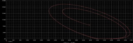
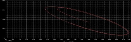
This is what is happening at low end with 16Hy and 40Hy
With 16Hy OT working elipse is so distorted. Almost loose the elipse shape. And more important, laying at X axes with "belly". To avoid this behaviour, we must decrease input voltage signal. And as the consequence we will lose the max undistorted power significantly.
With 40Hy OR primary there are no distorted working elipse, @20hz, there is no contact from working elipse and X axes. So there are no need to decrese input signal at the tube, and max power can reached at the low F.
Even with the 40Hy@20Hz static load line (in this case i put 3,5K) still is in the close range of 10-20 tolerance.
Attachments
Last edited:
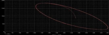
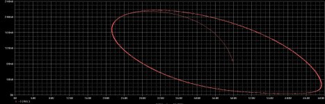
From the other side of BW @20KHz capacitive reactances taking place and there are the diference 3.5nF to 2nF
Almost the same thing occur. With 3.5nF wotking elipse is deformed, causing large distortion, leading to decrease input signal swing to avoid this...
But with 2nF working elipse looking good and without huge changes in the shape.
Almost the same thing occur. With 3.5nF wotking elipse is deformed, causing large distortion, leading to decrease input signal swing to avoid this...
But with 2nF working elipse looking good and without huge changes in the shape.
Attachments
It's a reason I like designing my transformer with leakage inductance dominant roll-off, taking advantage of the fact most speaker impedances increase with frequency. In practice with speakers loads, you get extended frequency response if the transformer is Ls dominant. The leftover tricks are taking care and predicting resonance amplitudes, shape and frequencies.
- Home
- Amplifiers
- Tubes / Valves
- Best 300B SE OPT?