In addition to the parts list on the prior page I went ahead and ordered the Audyn Q4 caps for all remaining positions (just the 10uf and 22uf) per Wolf's advice. (I know he said the 10uf NPE were OK but better safe than sorry.)
Audyn Cap Q4 10uF 400V MKP Metalized Polypropylene Foil Crossover Capacitor Part # 027-118 2 $4.31 $8.62
Audyn Cap Q4 22uF 400V MKP Metalized Polypropylene Foil Crossover Capacitor Part # 027-120 2 $8.57 $17.14
Once these arrive late this week possibly, I'll cut up a standard hardboard-backed clipboard in order to make two bases for the crossovers. These will fit inside the Hammond project boxes. A clipboard is the cheapest thing I could find. 2 bucks. Better than buying a 2x4' sheet at Home Depot.") I'll hot glue everything and use zip ties on most parts except the resistors. I'm pretty good with a soldering iron so it'll be a fairly neat affair.
I'll hot glue everything and use zip ties on most parts except the resistors. I'm pretty good with a soldering iron so it'll be a fairly neat affair.
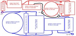
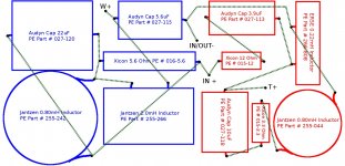
Any input about my crossover layout above is appreciated.
Audyn Cap Q4 10uF 400V MKP Metalized Polypropylene Foil Crossover Capacitor Part # 027-118 2 $4.31 $8.62
Audyn Cap Q4 22uF 400V MKP Metalized Polypropylene Foil Crossover Capacitor Part # 027-120 2 $8.57 $17.14
Once these arrive late this week possibly, I'll cut up a standard hardboard-backed clipboard in order to make two bases for the crossovers. These will fit inside the Hammond project boxes. A clipboard is the cheapest thing I could find. 2 bucks. Better than buying a 2x4' sheet at Home Depot.
I'll hot glue everything and use zip ties on most parts except the resistors. I'm pretty good with a soldering iron so it'll be a fairly neat affair.Any input about my crossover layout above is appreciated.
..health issues..
Bummer.
(..it hasn't been my best year either, nor the last.) Finally an update.
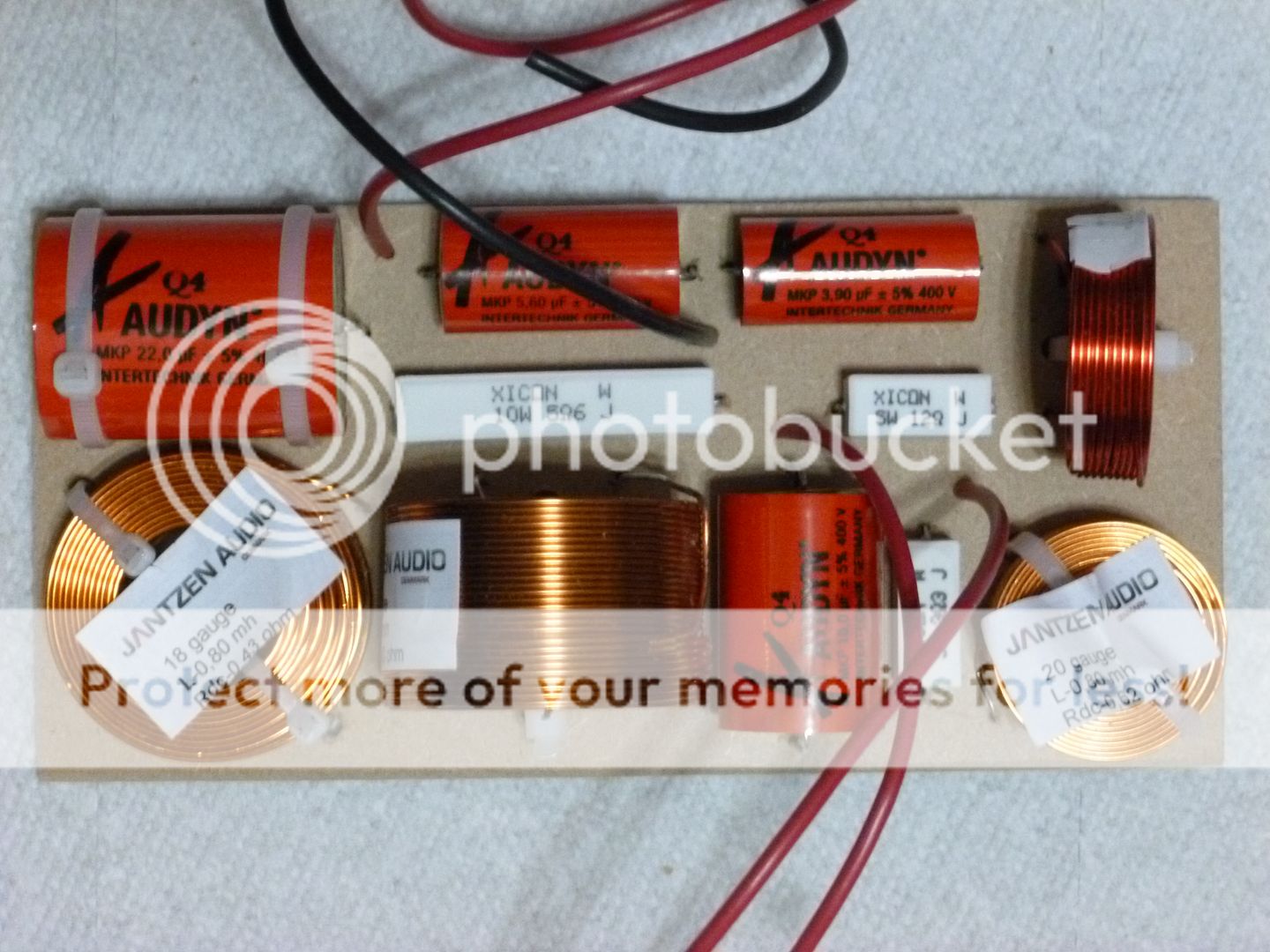
I drilled the holes in a piece of thin Masonite (I cut up a clip board) and mounted the crossover pieces for one crossover board. I used zip ties on the heavier parts but the smaller parts I felt would hold on fine with just the soldering on the back.
Here is a picture of the top:
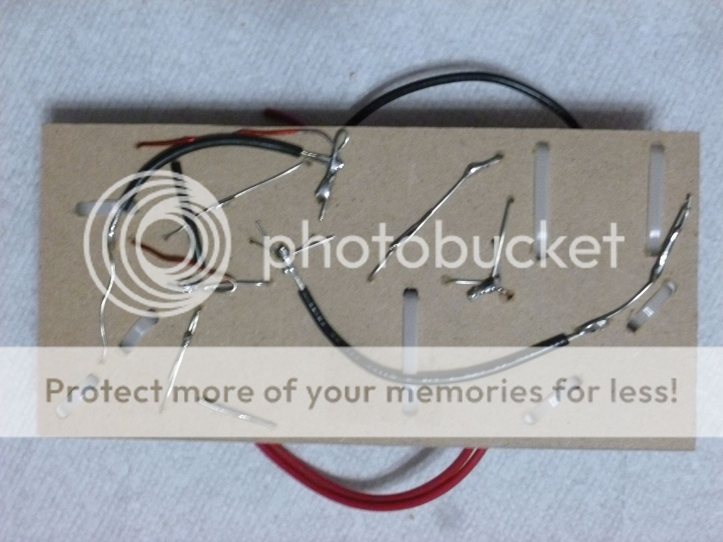
I then turned the board over and following the schematic posted on the first page of this thread I soldered the leads of all components together.
Here is a picture of the bottom:
Next step will be to use alligator clips to attach the crossover to the speaker binding posts and take some quick measurements to make sure it was put together more or less correctly.
If it measures more or less as expected based on the simulations posted on page one I'll build the second board and then work on drilling the holes for the binding posts in the project boxes wherein these will reside.
I drilled the holes in a piece of thin Masonite (I cut up a clip board) and mounted the crossover pieces for one crossover board. I used zip ties on the heavier parts but the smaller parts I felt would hold on fine with just the soldering on the back.
Here is a picture of the top:
I then turned the board over and following the schematic posted on the first page of this thread I soldered the leads of all components together.
Here is a picture of the bottom:
Next step will be to use alligator clips to attach the crossover to the speaker binding posts and take some quick measurements to make sure it was put together more or less correctly.
If it measures more or less as expected based on the simulations posted on page one I'll build the second board and then work on drilling the holes for the binding posts in the project boxes wherein these will reside.
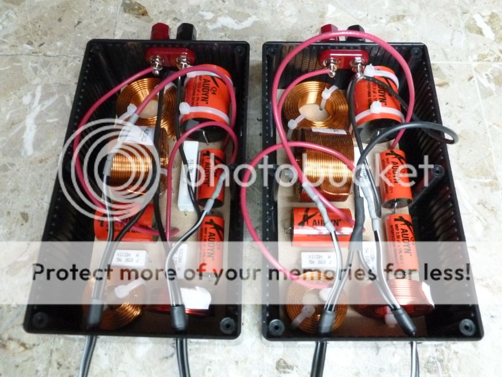
Picture of finished crossovers (sans the lids):
The speakers sound phenomenal. Thanks again for everyone's input.
An externally hosted image should be here but it was not working when we last tested it.
The speakers sound phenomenal. Thanks again for everyone's input.
The speakers sound phenomenal. Thanks again for everyone's input.
Good work - enjoy!

Very nice indeed! Your not going to try to bypass the 3.9uF cap with an Audyn True Copper? ;-) The one negative of that is that the Audyn TC start with rather large values, around 0.1uF.
I just checked. The Q4s are pretty inexpensive. Just for fun, try a pair of these in series with each 3.9uF:
Audyn Cap Q4 0.01uF
See if you find it worthwhile. Should be around $5 total.
Best,
Erik
Your not going to try to bypass the 3.9uF cap with an Audyn True Copper? ;-) The one negative of that is that the Audyn TC start with rather large values, around 0.1uF. I just checked. The Q4s are pretty inexpensive. Just for fun, try a pair of these in series with each 3.9uF:
Audyn Cap Q4 0.01uF
See if you find it worthwhile. Should be around $5 total.
Best,
Erik
Last edited:
Very nice indeed!
I just checked. The Q4s are pretty inexpensive. Just for fun, try a pair of these in series with each 3.9uF:
Audyn Cap Q4 0.01uF
See if you find it worthwhile. Should be around $5 total.
Best,
Erik
Placing those 0.01uF caps in series with each Q4 will effectively cut their capacitance value to almost nil, and really screw up his xover and sound. If you place them in parallel with the Q4s he already has, it really will only add to his present values by 0.01uF.
FWIW, I've tried bypasses at 0.01uF value of several types, and cannot hear the change if there is one. 0.1uF gets closer, but even then, using the same kinds of caps as 'bypasses' doesn't do much except lower ESR in the upper treble range, likely above the range of human hearing.
Later,
Wolf
Of course, placing the caps in series is not what I meant by "bypass." If you can't hear a difference, then you can't, and the exercise is pointless. Actually I should have suggested around 0.047uF for the 3.9 cap, making around a 1% difference.
Best,
Erik
The response is quite close actually to the sims, all speakers measure terribly in my room so bear that in mind but I'll try to post something up as soon as I can. The important thing is that they sound amazing - fast and detailed, nearly full range with lots of air on top but not hot.
Thanks for the continued discussion and well wishes. The health issues were not my own unfortunately, and we lost the battle.
The important thing is that they sound amazing - fast and detailed, nearly full range with lots of air on top but not hot.Thanks for the continued discussion and well wishes. The health issues were not my own unfortunately, and we lost the battle.
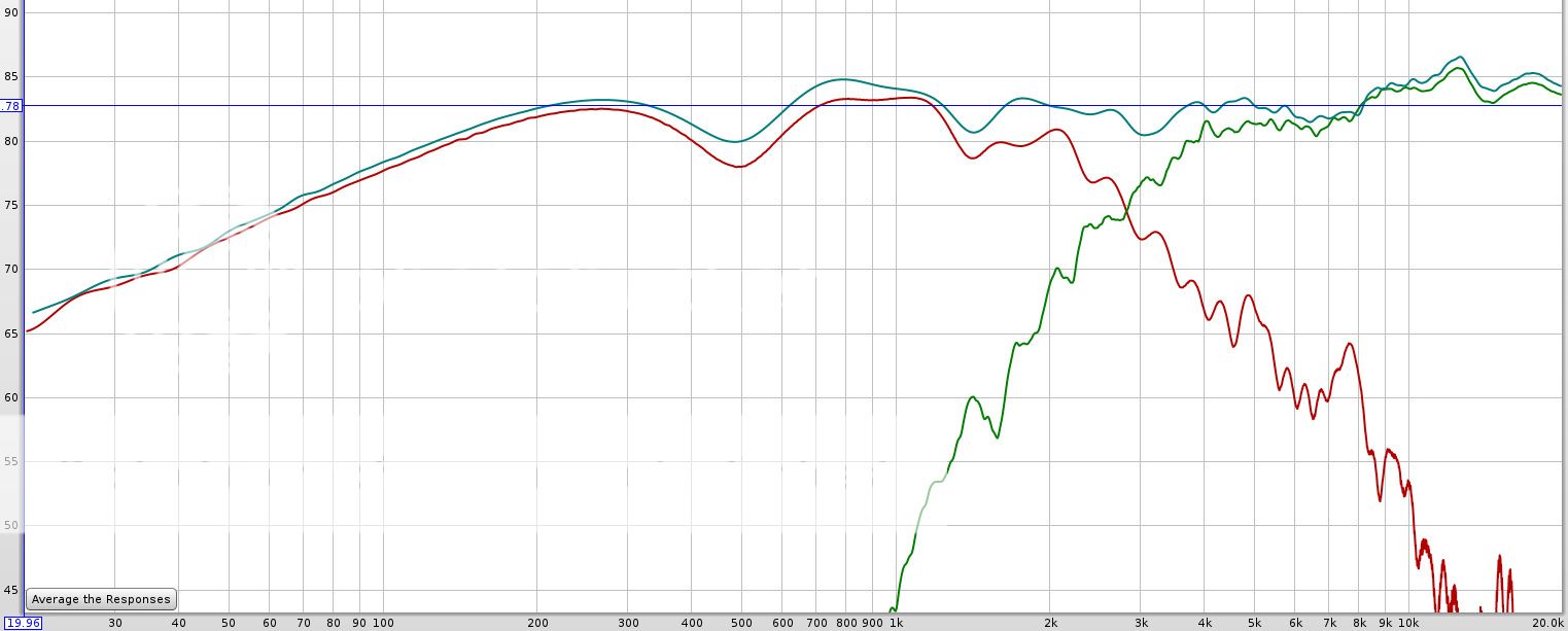
All right, here are some finished speaker measurements. These are quick and dirty, hand held mic in room with poor acoustics.
Smoothed 1/12th, Gated 2.7ms. Left speaker only. This is about 3 feet straight out from the speaker on the tweeter axis. The green line is the tweeter alone, the red line is the woofer alone, and the blue line is both together. These are all run through the crossover.
Next we have a quick measurement from the listening position. Smoothed 1/12th, Gated 2.4ms. Left speaker only. This is about 6 feet from the speaker and at ear height which is above the tweeter level by about a foot. As there is no toe-in the mic is off axis both vertically and horizontally by quite a lot.
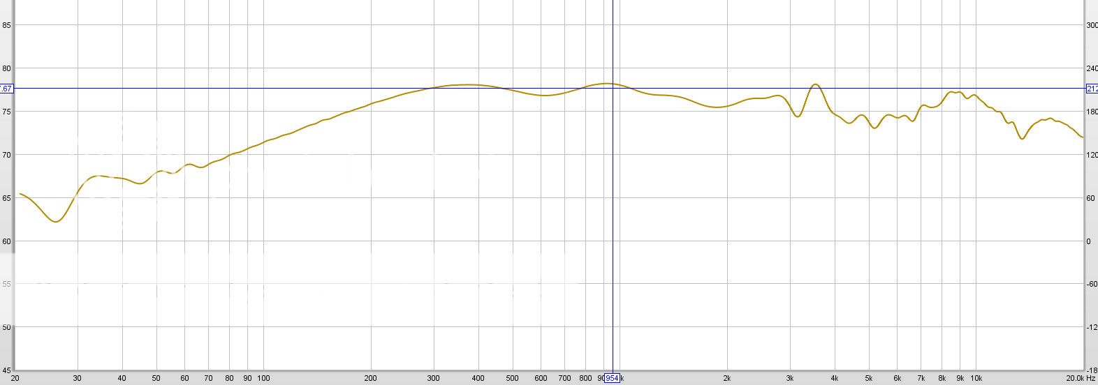
I think that considering how poorly commercial speakers measure in this room, these are doing quite well here.
Smoothed 1/12th, Gated 2.7ms. Left speaker only. This is about 3 feet straight out from the speaker on the tweeter axis. The green line is the tweeter alone, the red line is the woofer alone, and the blue line is both together. These are all run through the crossover.
Next we have a quick measurement from the listening position. Smoothed 1/12th, Gated 2.4ms. Left speaker only. This is about 6 feet from the speaker and at ear height which is above the tweeter level by about a foot. As there is no toe-in the mic is off axis both vertically and horizontally by quite a lot.
I think that considering how poorly commercial speakers measure in this room, these are doing quite well here.
- Status
- This old topic is closed. If you want to reopen this topic, contact a moderator using the "Report Post" button.
- Home
- Loudspeakers
- Multi-Way
- Ben's "Hi-Marks" Fullranger + Isodynamic Tweeter 2-Way Build Thread