Thanks, that's a lot easier for just looking than frds. 3.5ms ground reflection, looks like, pretty clean aside from that so if you got higher up... Blue lines are the full fft, red is no reflection.
I think someone said to include the floor bounce in the frd for xover design, what do you think.... gate at 4ms or 3.4ms? (gating higher then 3.8 or so makes some ripples, getting more severe as you go up) Thanks
")
The frequency and arrival time of the reflection depends on the height of speaker and mic and distance to the mic. Designing compensation of it in xo is not wise - and quite difficult in passive designs.
Outdoor measurements should be done further away than 36", at least 3' in my experience. If possible on grass or loose sand or the speaker facing up. Alike, make a simple turntable of two pieces of board and a pin/bolt. Then take horizontal off-axis measurements at least at 15, 30 and 45¤
Outdoor measurements should be done further away than 36", at least 3' in my experience. If possible on grass or loose sand or the speaker facing up. Alike, make a simple turntable of two pieces of board and a pin/bolt. Then take horizontal off-axis measurements at least at 15, 30 and 45¤
Last edited:
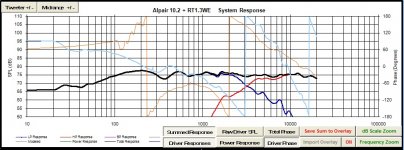
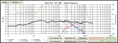
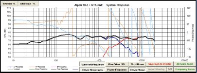
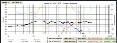
I plugged in the gated (4ms), smoothed (1/12th) outdoor measurements into PCD using the same crossover we designed in the prior few pages and everything seems to work as expected. So it seems the indoor measurements were fairly accurate. The first screenshot is on axis and the second one is vertically off-axis about +8.5 degrees (typical seated listening height). Good to go?
Attachments
I was the one telling you to include the floor bounce. The ripples
you are having in the woofer response are standing waves. Lining
was not enough. Make a roll of poly fiber stuffing and put it in
from top to about where vent lives, without choking its flow. From
side to side, not too lightly so you don't have to do it again. Then
repeat the measurements.
you are having in the woofer response are standing waves. Lining
was not enough. Make a roll of poly fiber stuffing and put it in
from top to about where vent lives, without choking its flow. From
side to side, not too lightly so you don't have to do it again. Then
repeat the measurements.
I plugged in the gated (4ms), smoothed (1/12th) outdoor measurements into PCD using the same crossover we designed in the prior few pages and everything seems to work as expected. So it seems the indoor measurements were fairly accurate. The first screenshot is on axis and the second one is vertically off-axis about +8.5 degrees (typical seated listening height). Good to go?
There ya go! That looks better....
Wolf
"Outdoor measurements should be done further away than 36", at least 3' in my experience."
Oops, that was supposed to be 5' (1,5m)
latest measurements look just fine! Below 3-500Hz is always very difficult to interprete. Measure with several locations, distances and gatings to find out how each hump and dip change!
Oops, that was supposed to be 5' (1,5m)
latest measurements look just fine! Below 3-500Hz is always very difficult to interprete. Measure with several locations, distances and gatings to find out how each hump and dip change!
..Good to go?
MUCH better - it (tweeter) has more pressure lower in freq. which will help with off-axis suck-out.
I'd still like to see a bit more pressure in the mid's however.
I'd still like to see a bit more pressure in the mid's however.
What would I be looking for there?
What would I be looking for there?
There are two areas that I'm looking at:
1. is the potential a lack of mid correction for the small baffle - which would likely be around 700 - 800 Hz or so, BUT I don't know how it's being modeled, so if it's already factored-in then it's very good.
2. the response between 1.1 kHz and 2.5 kHz on the Alpair should be shelved by about 2 db. Without this it will still sound "forward" and lack a bit in depth of field.
Last edited:
Oh, BTW - here is a good example of the design/testing process for loudspeakers on pages 4 & 5:
http://kimmosaunisto.net/Software/VituixCAD/VituixCAD_help_013.pdf
http://kimmosaunisto.net/Software/VituixCAD/VituixCAD_help_013.pdf
There are two areas that I'm looking at:
1. is the potential a lack of mid correction for the small baffle - which would likely be around 700 - 800 Hz or so, BUT I don't know how it's being modeled, so if it's already factored-in then it's very good.
2. the response between 1.1 kHz and 2.5 kHz on the Alpair should be shelved by about 2 db. Without this it will still sound "forward" and lack a bit in depth of field.
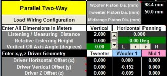
1) My understanding is that since I have taken actual in-box measurements and set the offsets correctly that the simulation in PCD should be fairly accurate as the end result.
2) See attached, on axis and vert. off axis respectively. Better? Or worse?
Attachments
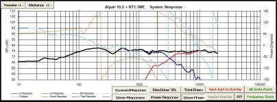
Better, but it's still a "touch" prominent/loud at 1-1.3 kHz by about 1 db. (..it's not something I'd "sweat" though.)
Yes, but is the model showing a 2 meter response, or a 1 meter response? If it's 2 meters then it's excellent. If it's 1 meter then not so much.
Yes, but is the model showing a 2 meter response, or a 1 meter response? If it's 2 meters then it's excellent. If it's 1 meter then not so much.
Last edited:
Better, but it's still a "touch" prominent/loud at 1-1.3 kHz by about 1 db. (..it's not something I'd "sweat" though.)
Yes, but is the model showing a 2 meter response, or a 1 meter response? If it's 2 meters then it's excellent. If it's 1 meter then not so much.
2 meter, once the offset was found I let PCD use its default distance for the sim.
Glad you like the latest sim, it uses 1 less part than the one on the prior page.
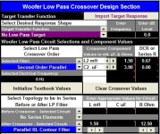
An RL contour filter instead of the notch.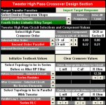
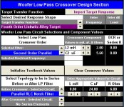
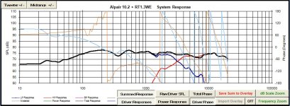
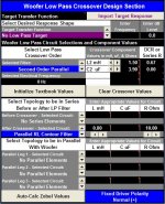
Well my friends, I think I'll go with the following attached design. It is similar to the ones posted above but is a little bit lower in the 1K area as Scott was saying might be desirable. This design also economizes by taking advantage of quantity price breaks on a couple parts and using a two-piece contour filter on the woofer instead of a three-piece notch filter. As per usual I have two system response graphs, the first is on-axis and the second off-axis vertically by 8.53 degrees, both at a simulated listening distance of 2 meters.
Attachments

That's very good, but I'd do a range of verticals (every 2 degrees or so) if I were you to make sure it's decent within +/- 15 degrees (at a minimum). You can "adjust" that vertical range based on placement and listening position - but it should still be a minimum 30 degree vertical window (with 15 "steps").
Last edited:
That's very good, but I'd do a range of verticals (every 2 degrees or so) if I were you to make sure it's decent within +/- 15 degrees (at a minimum). You can "adjust" that vertical range based on placement and listening position - but it should still be a minimum 30 degree vertical window (with 15 "steps").
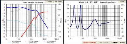
There is a large dip near the crossover frequency (3300 roughly) at the extreme ends of your 30 degree (+/- 15) vertical window. I'm not sure it's possible to design a crossover unaffected by that issue. It's not bad within a 20 degree (+/- 10) window vertically. The sim shows that the horizontal off-axis is good with just a little high frequency rolloff. I have attached the PCD session file and the frd/zma so you can check it out. The .txt extension has to be removed on these files.
Attachments
-
contour-and-notch5.csp.txt937 bytes · Views: 30
-
merged-alpair-smoothed-4ms-gated-min-phase.frd.txt12.7 KB · Views: 27
-
merged-rt1.3we-smoothed-4ms-gated-min-phase.frd.txt9.8 KB · Views: 23
-
markaudio-alpair-10.2_simmed_minphase.zma.txt13.2 KB · Views: 29
-
HiVi RT1.3_minphase.zma.txt2.2 KB · Views: 26
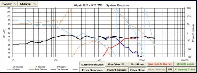
Is there still a good forward lobe angle where you have good phase tracking through the xover region, like you did in post #91? They are 30° off at xover in what you call 'on-axis' above.
Relatedly, that large dip is the null at the acoustic xover frequency. Its location above and below the forward lobe is set by the distance between drivers relative to the frequency.
Relatedly, that large dip is the null at the acoustic xover frequency. Its location above and below the forward lobe is set by the distance between drivers relative to the frequency.
Is there still a good forward lobe angle where you have good phase tracking through the xover region, like you did in post #91? They are 30° off at xover in what you call 'on-axis' above.
Thanks for the reminder. The deepest null is still at +2.86 vertically and here is the result with the latest xover:
Attachments
- Status
- This old topic is closed. If you want to reopen this topic, contact a moderator using the "Report Post" button.
- Home
- Loudspeakers
- Multi-Way
- Ben's "Hi-Marks" Fullranger + Isodynamic Tweeter 2-Way Build Thread