Oh- and a single cap will not be enough on that tweeter. I guarantee it. Bare minimum is second order, but to get good summation may require 3rd/4th electrical. If you are thinking that fewer parts are better, you have to realize that fewer with planars is not the same as fewer with the robust dome tweeters or benignly graphed midbasses. Sometimes more parts are required.
'Minimalism with respect to necessity' is my motto for parts count.
Later,
Wolf
Good catch!
Didn't look close enough at it.

It really needs power/distortion modeling.
Good catch!
Didn't look close enough at it.
It really needs power/distortion modeling.
From Zaph (FR/H/V/Z/HD/CSD):


I used a 4th order electrical with it at 3k.
Later,
Wolf
Oh- and a single cap will not be enough on that tweeter. I guarantee it. Bare minimum is second order, but to get good summation may require 3rd/4th electrical.
Thanks for chipping in here Wolf
")
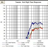
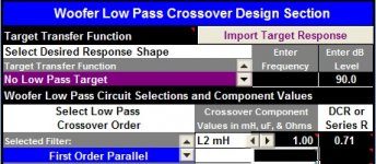
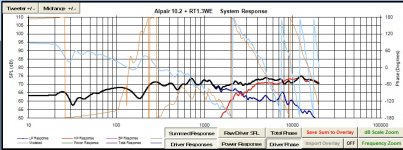
The reason that I thought I could get away with just the cap is because I set the target transfer function to "second order butterworth target" and then used a value of cap and resistor that matched that curve on the graph more or less. See picture named "tweeter2.jpg" attached, green line is the target response for second order at 2.8K. Also I was able to play the sweep down to 100 Hz several times on the measurements with no ill effects. I know simulations are not the whole story and I respect your experience I just wanted to explain my perhaps flawed line of reasoning.
Side note, I think I'm finding that inverting the tweeter polarity helps with making the response a bit flatter up top.
Attachments
Thanks for chipping in here Wolf
The reason that I thought I could get away with just the cap is because I set the target transfer function to "second order butterworth target" and then used a value of cap and resistor that matched that curve on the graph more or less. See picture named "tweeter2.jpg" attached, green line is the target response for second order at 2.8K. Also I was able to play the sweep down to 100 Hz several times on the measurements with no ill effects. I know simulations are not the whole story and I respect your experience I just wanted to explain my perhaps flawed line of reasoning.
Side note, I think I'm finding that inverting the tweeter polarity helps with making the response a bit flatter up top.
Since the tweeter (yes, pretty much any chambered tweeter in fact) is a sealed system, it has an inherent 12dB/octave rolloff. In fact, your 1st order addition would eventually asymptote to 3rd order below the Fc of the cap. 6+12 = 18dB/oct. This is why using a 12dB elec filter results in 4th order acoustic rolloffs for most tweeters in most typical applications.
In effect, the cap will not provide much protection since the tweeter almost has its natural curve still employed. Also be advised that a 2nd order or 4th order electrical filter will have more protection for the tweeter versus a 1st or 3rd order network. This is due to the coil in parallel with the tweeter.
I can't see the polarity making any difference in a typical xover system in terms of top-end extension. It will make a difference around the xover region in blend with the woofer.
Later,
Wolf
Yes- that was a measured .zma, and I would not use an axis between the drivers.
The issue is that he is listening above the tweeter axis, so that is where the design
axis should be. I would personally just use the vertical off axis response to simulate
where the listener will be listening. If it's 5 degrees up, use that- and so on.
The difference between those 2 axis in Ben's scenario is 2,18 degrees.
We are fortunate that human hearing is so much more sophisticated than the one of a mic.
How many times do we stand up and walk away from the sweet spot passing through lobes
regions where is massive cancelation in XO region and nothing happens.
Your advice does make sense as long as the one accepting it does not abuse it,
like choosing a listening spot where you can't avoid sound cancelation and then
makes a mistake by changing polarity to make it look right again.
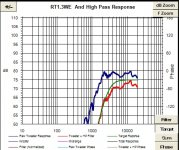
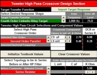
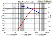
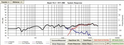
Is this better? (See attached screenshots from PCD.) I used a second order on the tweeter which seems to be within the 4th LR target as shown in the attachments. Since listener's ear will probably be about .3m above the tweeter 2m away I thought the 8.5degrees setting worked for the simulation.
Attachments
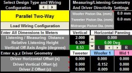
Set the piston diameter for the height of the ribbon when simulating off-tweeter-axis vertically, and to the width of the ribbon for horizontal sims. Or, better yet, look at off-axis measurements to find piston diameter that matches best in each case. Set W piston diameter to cone diameter + a little of the surround.
Also, keep in mind you are going 8.5° above the tweeter axis, which is already a few degrees above the acoustic center of the speaker. Might want to incorporate some tilt into the cabinet instead of skewing your forward lobe so far?
Also, keep in mind you are going 8.5° above the tweeter axis, which is already a few degrees above the acoustic center of the speaker. Might want to incorporate some tilt into the cabinet instead of skewing your forward lobe so far?
DT has some good advice.
As you have it, I would at least pad the tweeter a bit more and maybe a little more inductor on the woofer to tilt the response flatter. As you have it, it will sound quite hot on top.
Other than that- using second order electrical may require a higher xover point if it sounds stressed.
Later,
Wolf
As you have it, I would at least pad the tweeter a bit more and maybe a little more inductor on the woofer to tilt the response flatter. As you have it, it will sound quite hot on top.
Other than that- using second order electrical may require a higher xover point if it sounds stressed.
Later,
Wolf
Other than that- using second order electrical may require a higher xover point if it sounds stressed.
Later,
Wolf
If he does that he's going to get "suck-out" off-axis.. Even as it is (with the more recent model), it's questionably in that regard.
The Mark Audio driver has almost 6db of loss at only 30 degrees at just 2 kHz.
-LOW and "STEEP" for that high-pass.
We do listen to the first arrival as well as the room reflections, but the first arrival is the most important. Using a planar low and steep isn't really something that works well in most cases. Most planars are truly 3k+.
I think he'll be fine, even if he has to raise the xover point or go steeper.
Wolf
I think he'll be fine, even if he has to raise the xover point or go steeper.
Wolf
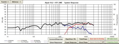
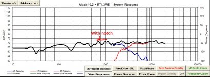
It should be pretty obvious when you click the vertical panning buttons, because it will be simulating the off-axis response of diaphragms with a size instead of point sources.I adjusted the woofer piston dia to 98.4 mm and the tweeter piston dia to 50mm. Don't think it made much difference in the sim nothing obvious to me anyway.
Here attached is the woofer with "more inductor", 2 mH. More suckout at 1.5K I think.
Off-axis is also where the "suckout" referred to earlier will be, btw (where the woofer dispersion is narrower than the HF, also punctuated by where the drivers fall out of phase at xover off-axis vertically). The dip you're creating above is just differences in the ribbon output and/or phase tracking on the design axis - different thing.
Last edited:
Off-axis is also where the "suckout" referred to earlier will be, btw (where the woofer dispersion is narrower than the HF, also punctuated by where the drivers fall out of phase at xover off-axis vertically).
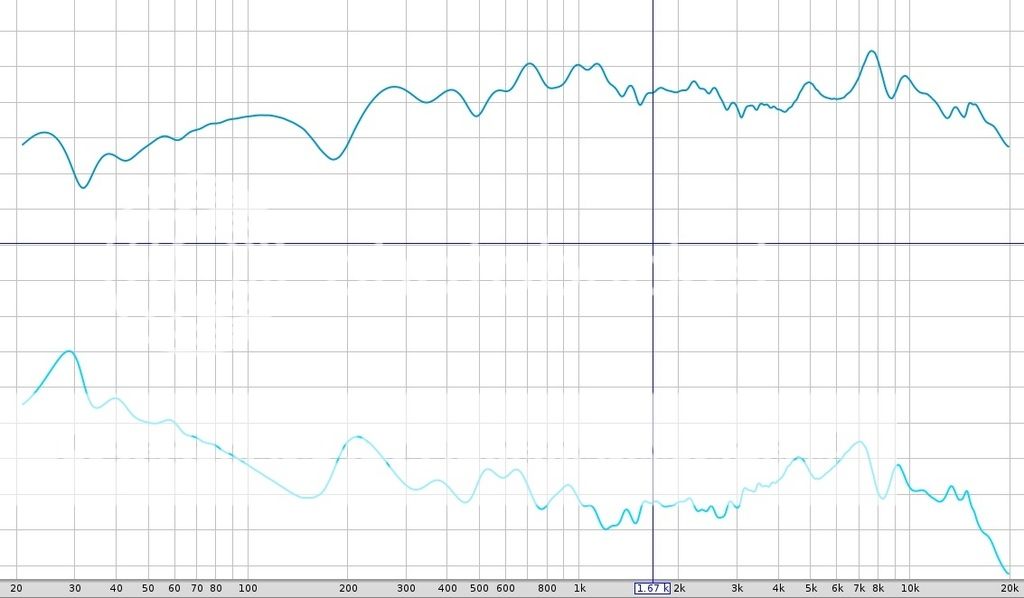
The "trough-like" dip that appears off-axis centered at about 1.7 kHz for this loudspeaker - and this is just the horizontal response.
Attachments
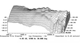
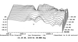
If we look at my measurements again we can see that the dip at 1.5-1.7K is there in the close mic of the woofer (mic on woofer axis and about 1.5" away from dustcap):
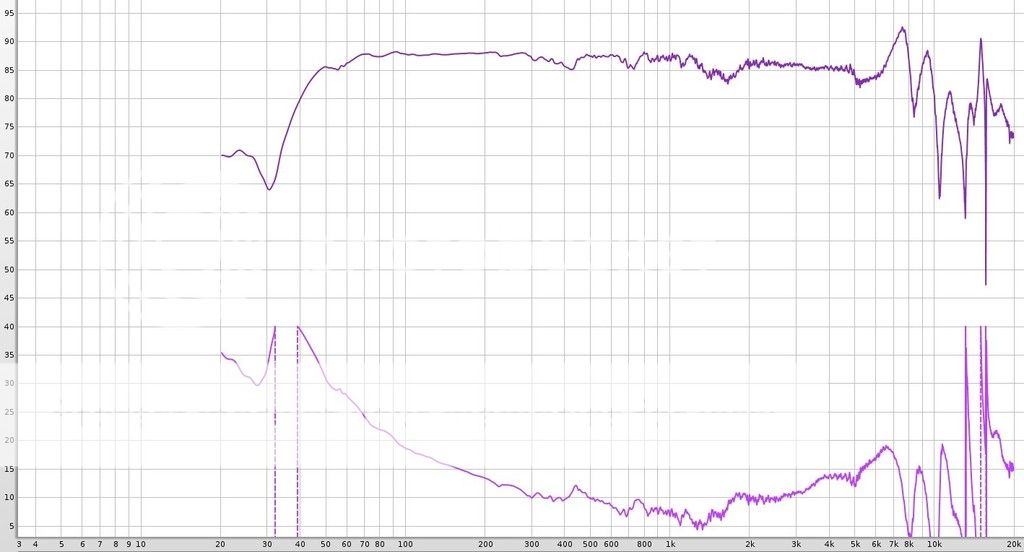
....and definitely there with both drivers playing the sweep (mic on tweeter axis and 3' away):

...but oddly not really there with just the woofer being measured (mic on tweeter axis again and 3' away):
....and definitely there with both drivers playing the sweep (mic on tweeter axis and 3' away):
...but oddly not really there with just the woofer being measured (mic on tweeter axis again and 3' away):
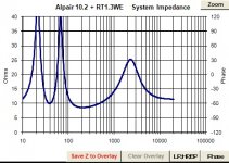
Yep, probably a little something in the impedance around there too?If we look at my measurements again we can see that the dip at 1.5-1.7K is there in the close mic of the woofer (mic on woofer axis and about 1.5" away from dustcap):
I'm pretty sure that's cancellation from the drivers being 180° in phase there.....and definitely there with both drivers playing the sweep (mic on tweeter axis and 3' away):
I think it's still there (see below). Again, though, scott is talking about something else entirely, a mismatch in polar pattern at xover....but oddly not really there with just the woofer being measured (mic on tweeter axis again and 3' away):
Attachments
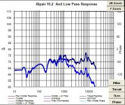
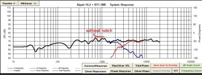
...And here attached is the woofer with just a .7 mH inductor. Seems better. Maybe I'm missing something.
More coil on woofer, and pad tweeter, unless you don't want any bass.
This is call BSC (baffle step comp). Tilt it down to flatten out the loss in bass, and pad the tweeter to balance the level.
Later,
Wolf
Ben,
I have a similar issue with a driver of mine in a smaller 2 way system.
Mine has a surround resonance and there is no way I could have made
it better with a XO filter. I have to live with the fact there is a small
dip.
Keep the XO frequency higher(ribbon). In order to do that you don't have much
choice. Larger coils are not the answer, smaller ones with a parallel RLC
before the LP or a series one in parallel with the driver is the answer for the
baffle step.
Because of cone breakup which affects the tweeter output, single coil
is a no go. You can get around it with a 2nd order electrical or a single
coil and a series RLC in parallel with the woofer to get rid of the HF junk.
Typical values are the smaller ones.
- Status
- This old topic is closed. If you want to reopen this topic, contact a moderator using the "Report Post" button.
- Home
- Loudspeakers
- Multi-Way
- Ben's "Hi-Marks" Fullranger + Isodynamic Tweeter 2-Way Build Thread