All right, measurement results as follows:
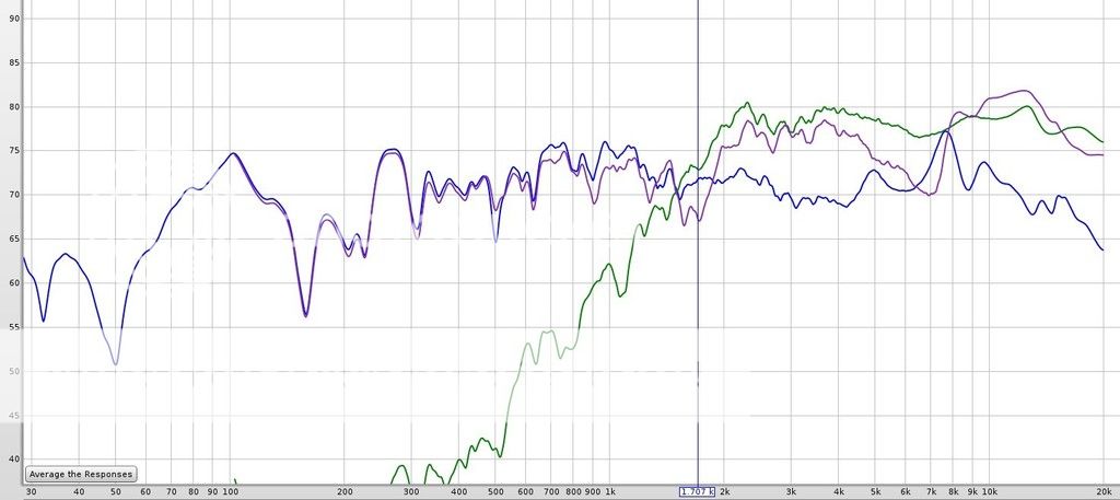
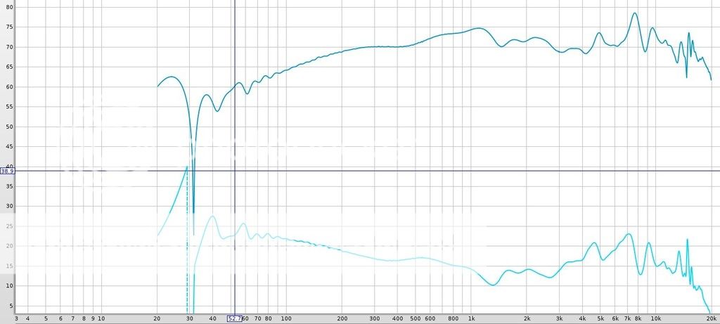
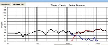
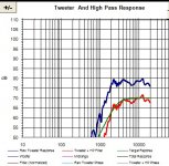
These are in-box measurements all smoothed 1/12, the blue line is the Alpair 10.2, the green line is the RT1.3 Tweeter and the pink line is both played together:
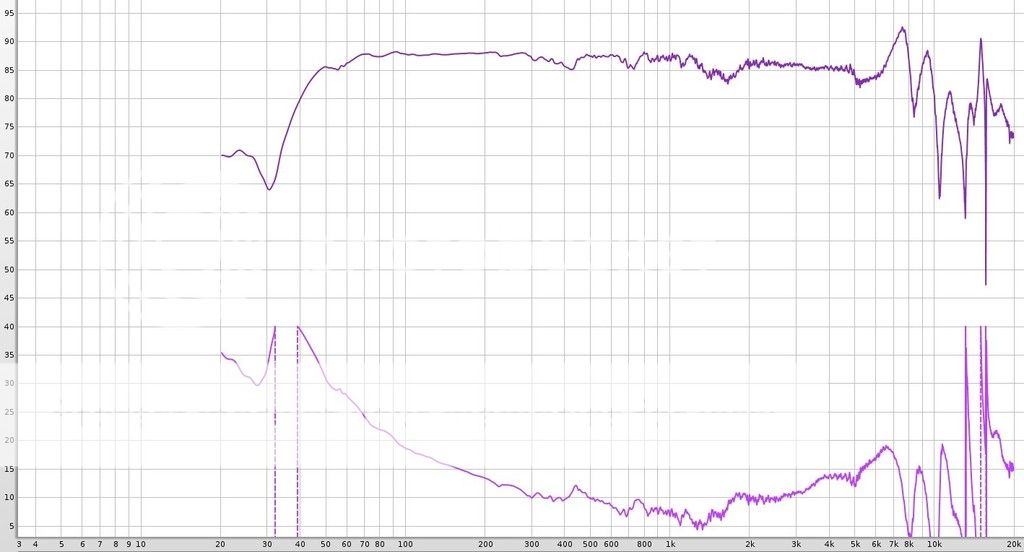
I also close-mic'ed the woofer to show there are no problems with the box (no smoothing!):
Notes on these tests:
- speaker on 23" stands
- woofer 30" from floor
- tweeter 36" from floor
- speaker 36" from mic
- receiver setting -25.0 db
- mic at tweeter height, 36"
- woofer sweep 20-20k
- tweeter and combined sweep 100-20k
- changed above setup for close mic woofer at 1.5" distance centered on woofer
So, these are un-gated (at the default 500ms), not sure what to do with the gating..... Jeff says 8ms but not sure that's good for my small workroom..... do you guys want to see the impulse response for any of these measurements to help me decide at what time frame I should gate?
These are in-box measurements all smoothed 1/12, the blue line is the Alpair 10.2, the green line is the RT1.3 Tweeter and the pink line is both played together:
I also close-mic'ed the woofer to show there are no problems with the box (no smoothing!):
Notes on these tests:
- speaker on 23" stands
- woofer 30" from floor
- tweeter 36" from floor
- speaker 36" from mic
- receiver setting -25.0 db
- mic at tweeter height, 36"
- woofer sweep 20-20k
- tweeter and combined sweep 100-20k
- changed above setup for close mic woofer at 1.5" distance centered on woofer
So, these are un-gated (at the default 500ms), not sure what to do with the gating..... Jeff says 8ms but not sure that's good for my small workroom..... do you guys want to see the impulse response for any of these measurements to help me decide at what time frame I should gate?
Good, the standing waves are attenuated, but not completely gone.
If they were, the straight line would be in those places.
I'll repeat myself, the time window should be long enough so you
can see what the baffle step looks like and decide what to do about it.
I would let it show the floor bounce.
Now do the work on finding the relative acoustic offset in the way Jeff
describes it. You should turn your measurements into frd's and zma's
and post it here in a zipped file so we can do the same. The minimum phase
has to be included in the measurements or calculated separately.
If you can measure the impedance of the drivers in the box, the better
and more precise the simulation will be.
So, the woofer centre from the tweeter centre is exactly 6" and the mic
was positioned in level with the tweeter centre height?
Attachments
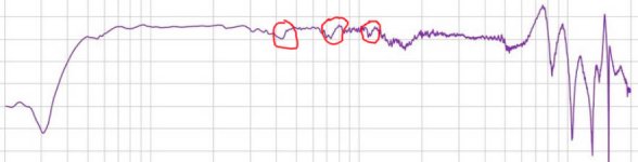
Good, the standing waves are attenuated, but not completely gone.
If they were, the straight line would be in those places.
I'll repeat myself, the time window should be long enough so you
can see what the baffle step looks like and decide what to do about it.
I would let it show the floor bounce.
Now do the work on finding the relative acoustic offset in the way Jeff
describes it. You should turn your measurements into frd's and zma's
and post it here in a zipped file so we can do the same. The minimum phase
has to be included in the measurements or calculated separately.
If you can measure the impedance of the drivers in the box, the better
and more precise the simulation will be.
So, the woofer centre from the tweeter centre is exactly 6" and the mic
was positioned in level with the tweeter centre height?
1) So you still think some poly fill should be added inside the cabinets then? I could take out the tweeter and feed a rope of poly fill in there. I just worry about stripping the screws (they don't grab the hex key very well but it would be easier than taking out the woofer and losing the T-nuts in there....again) or somewhat blocking the ports both of which could happen. I think maybe if I pull the poly fill apart and make it loose it should not block too much airflow to the ports.
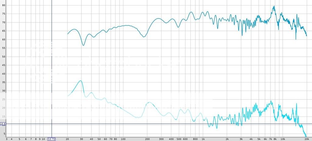
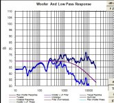
2) I used the calculator at https://mehlau.net/audio/floorbounce/ and it tells me that the floor bounce occurs at 2.86ms on the woofer measurement:
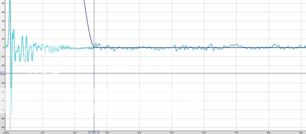
I have it gated at 2.6ms as you can see which means that frequencies below 385Hz would not be accurately represented but I don't think that's a big issue.. not sure what the baffle step implications might be. Jeff said he gates at 8ms in his guide and even though my room is probably smaller than Jeff's do you think I should just go for 8ms? Take a peek at the impulse response above. Here is the SPL at 2.6ms gating (no smoothing):
and at 8ms...
3) Yes following the procedure you showed me in Jeff's PDF and then posting the frd and zma was pretty much my plan I just got hung up on measurement techniques and how to properly gate the measurement.
")
4) Yes, the tweeter and woofer are about 6" apart on center and the mic was at tweeter level for all but the close mic measurement.
Also do you think it would be useful to splice in the close mic measurement below a certain frequency and if so how?
In any case thanks for all of your help.
Last edited:
1)
So you still think some poly fill should be added inside the cabinets then?
Also do you think it would be useful to splice in the close mic measurement below a certain frequency and if so how?
In any case thanks for all of your help.
No, I don't think you should be messing around with the pollyfill right now.
Maybe later when you are done and want to make it perfect.
Nevermind the splicing od the near field and far field meaurements.
This isn't important for a succesful design, only to make it look better
on the paper.
Increase the time window, don't feel bad because of the extra wiggles in
the graph. Your biggest concern should be how the woofer and tweeter will
add in the XO region. The bass reflex tuning you can change afterwards.
You'll succeed!
Increase the time window, don't feel bad because of the extra wiggles in
the graph.
OK I'll just use the 8ms gating and proceed. Thanks.
If you do math with those measurements, 2.6 ms is the difference in shortest path length from drivers to floor to mic vs. drivers to mic. Assuming the ceiling is not 6', you can get a larger clean time window by raising the speaker.- woofer 30" from floor
- tweeter 36" from floor
- speaker 36" from mic
P.S., RE: Troels' mic fussiness, nothing wrong with being careful, but unlike most of his other examples, the reflection back toward the capsule from this style of mic mount when it's also a boom angled forward (instead of 90° shown) is just about nil, nothing remotely like the cardboard square shown measured on that page.


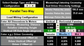
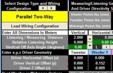
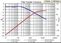
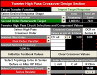
All right friends, I followed Jeff Bagby's Guide "How To Use Passive Crossover Designer To Find The Relative Acoustic Offset". Here below is a screenshot of the results. The simulation black line is as close to the measurement of 'both drivers playing the sweep together' (shown as the gray line) as I could get it with these offset settings:
Listening / Measuring Distance: 0.914
Driver Vertical Offset Woofer 1: 0.152
Driver Z Offset (z) Woofer 1: -0.0085
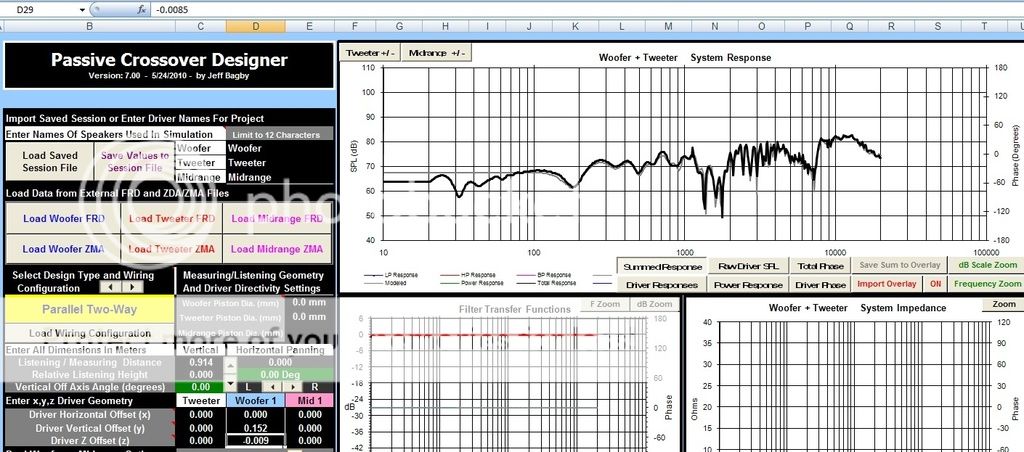
I have also attached the in-box FRD files with minimum phase extracted along with the simmed ZMA files again so you guys will have it all in one place if you want to help. (Much appreciated.) Just remove the .txt part from the file names. Next I'll try to work up a (hopefully simple) crossover myself in PCD and post it for critique.
Listening / Measuring Distance: 0.914
Driver Vertical Offset
Woofer 1: 0.152Driver Z Offset (z) Woofer 1: -0.0085
I have also attached the in-box FRD files with minimum phase extracted along with the simmed ZMA files again so you guys will have it all in one place if you want to help. (Much appreciated.) Just remove the .txt part from the file names. Next I'll try to work up a (hopefully simple) crossover myself in PCD and post it for critique.
Attachments
Thanks Ben so far for the files. Could you include the frd of both of the
drivers so I can check the offset as well. You have set the positive value
for the Y axis of the woofer, it should be negative(-) because your main
measurement axis is the tweeter centre. Fill in the woofer and tweeter
piston diameter fields.
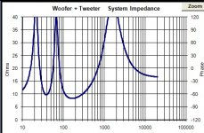
The dcr of the ribbon according to zma is 6,3 which puzzles me.
Values in the lower frequency regions is almost identical with the
higher midrange regions.The manufacturer says 5,4. Z offset will
probably be greater than 0,9 cm or maybe not.
There is no official value for the Sd of the ribbon.
drivers so I can check the offset as well. You have set the positive value
for the Y axis of the woofer, it should be negative(-) because your main
measurement axis is the tweeter centre. Fill in the woofer and tweeter
piston diameter fields.
The dcr of the ribbon according to zma is 6,3 which puzzles me.
Values in the lower frequency regions is almost identical with the
higher midrange regions.The manufacturer says 5,4. Z offset will
probably be greater than 0,9 cm or maybe not.
There is no official value for the Sd of the ribbon.
Last edited:
Thanks Ben so far for the files. Could you include the frd of both of the
drivers so I can check the offset as well. You have set the positive value
for the Y axis of the woofer, it should be negative(-) because your main
measurement axis is the tweeter centre. Fill in the woofer and tweeter
piston diameter fields.
The dcr of the ribbon according to zma is 6,3 which puzzles me.
The dcr value with this kind of tweeter is almost identical at 200Hz
or 2kHz.The manufacturersays 5,4. Z offset will probably be greater
than 0,9 cm.
Thanks for double checking me I appreciate it. I changed the woofer vertical offset from positive to negative value and the graph did not change. I have attached the measurement of both drivers at once as requested.
(file name: both-together-in-box_minphase.frd.txt)I got that zma for the tweeter from fellow diy'er Wolf/Wolf_Teeth but I ran it through the minimum phase function in Response Modeler. Maybe that was a boo-boo. I have also attached Wolf's original file without running it through the minimum phase function. Do you think that one makes more sense? (file name: HiVi RT1.3.zma.txt)
Attachments
Those are the same files. Your calculation of minimum phase only adds
the values of phase which doesn't change anything in the Impedance column.
Wolf has probably measured it, so let's leave it as it is. Can you check the dcr
of the ribbon with a multimeter? That negative Y offset value will be useful
when you will check the off-axis response.
the values of phase which doesn't change anything in the Impedance column.
Wolf has probably measured it, so let's leave it as it is. Can you check the dcr
of the ribbon with a multimeter? That negative Y offset value will be useful
when you will check the off-axis response.
I used the function of 1/6th octave smoothing in RM for better vision
in PCD. Your Z offset looks okay. Try to do something with these. Main
response simulation axis I chose is the middle point on the tweeter to woofer
ctc distance.
in PCD. Your Z offset looks okay. Try to do something with these. Main
response simulation axis I chose is the middle point on the tweeter to woofer
ctc distance.
Attachments
Can you check the dcr
of the ribbon with a multimeter?
The tweeter looks like 6.4 ohms and the woofer is around 7.5 ohms.
Main
response simulation axis I chose is the middle point on the tweeter to woofer
ctc distance.
Is that good? The ear will be above tweeter level on these.
Here are the frd files smoothed 1/12th octave if anyone prefers those over the un-smoothed ones.
Attachments
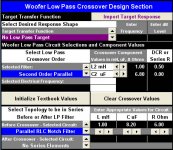
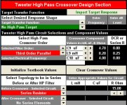
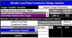
In the interests of keeping component count to a minimum, I have a design using three parts. While it's not quite as good as Lojzek's suggestion I like using fewer parts. Please let me know what you all think of it or if it can be improved using the same number of parts. Thanks Screenshots from PCD attached.
Screenshots from PCD attached.Attachments
Is that good? The ear will be above tweeter level on these.
The simplest answer I can think of, I am getting the best results or at least
I'm convinced to be getting the best results this way. People often check their
work by observing driver phase and if they are reasonably close together
then it's likely things will work out fine.
Do whatever feels like the right thing to do and thanks for the dcr data, they are
in agreement with Wolf's measurement of ribbon impedance.
edit: You forgot to change the listening(measuring) distance to the actual one
Last edited:
edit: You forgot to change the listening(measuring) distance to the actual one
Well my friend the reason I did that is that 2 meters is about where the listening position is. In Jeff Bagby's guide at the end it says:
.....use the offsets that you have already found
for your crossover design work. You may change the listening distance to 2.0 Meters or any other distance you
desire now, and begin to work on your crossover design. Passive Crossover Designer will accurately calculate the
summed frequency response on any axis you choose based on the offsets that have been entered, and you will
find that the final response in your Passive Crossover Designer Model will match your final measured response
exceptionally well.
Yes- that was a measured .zma, and I would not use an axis between the drivers. The issue is that he is listening above the tweeter axis, so that is where the design axis should be. I would personally just use the vertical off axis response to simulate where the listener will be listening. If it's 5 degrees up, use that- and so on. I always design on the tweeter axis so you don't lose any upper treble due to rolloff, and the planars have worse than dome tweeter vertical dispersion anyway. So- use 0,0,0 for the tweeter, and offset from there, whilst designing at an angle that approximates the listening axis.
Oh- and a single cap will not be enough on that tweeter. I guarantee it. Bare minimum is second order, but to get good summation may require 3rd/4th electrical. If you are thinking that fewer parts are better, you have to realize that fewer with planars is not the same as fewer with the robust dome tweeters or benignly graphed midbasses. Sometimes more parts are required.
'Minimalism with respect to necessity' is my motto for parts count.
Later,
Wolf
- Status
- This old topic is closed. If you want to reopen this topic, contact a moderator using the "Report Post" button.
- Home
- Loudspeakers
- Multi-Way
- Ben's "Hi-Marks" Fullranger + Isodynamic Tweeter 2-Way Build Thread