Hello !
Report on Cherry's NFB LM1875.
It's the zobel network that I missed!
Another note on Zobel for this attempt, put that Zobel network as close as possible to the chip (well, this has been recommended previously by senior members of this forum).
This is different from my previous build with 12-0-12 tranny, I put the zobel at the speaker terminal instead of near the chip.
Any further thought on the optimum Zobel network values?
Thanks for your suggestions.
(Edited)
Checking the gain.
1. Digital multimedia player, headphone output, gain is 0.464/0.02 = 23.2
2. USB DAC line out, gain is 1.044/0.44 = 23.73
Last edited:
Neville Thiele (according to the Cherry article) gave two versions of his Output Network.
Cherry tells us they both work.
The Two versions are:
a.) R+C in series shunting the Output Back to the Output Stage. Followed by a L and R in parallel to feed the output to the load.
b.) L and R in parallel to feed to output onward. Followed by a capacitor shunting the output back to the Output Stage.
Cherry expands on this and his article is well worth reading.
Note that in b. that when the inductor is at high impedance the R and C are effectively in series. They still operate as the conventional Zobel snubber .
Many say that b. version cannot work. Balderdash. It's their implementation that prevents b. from working.
The output Zobel depends on low impedance at high frequency and this demands that the Zobel uses short compact routes to tie the Output back to the Stage (effectively back into the local decoupling).
If b. is located at the far end of 12" cable that is not close coupled to the return cable, then you have added at least another 200nH (and more probably >400nH) of inductance before the C
edit:
remove the .txt from the file name to leave .xls It is an excel spreadsheet.
My open office shows the graphics slightly corrupted but it was created in a very old version of excel and all excel should read and display the file correctly.
Attachments
Last edited:
Thanks.
Currently I am using 10R + 10 nF for my Zobel. Is it too low? But it works in improving the sound, I mean, without it the sound just got distorted and those are the components I have.
I wonder what makes the zobel network is so important in this implementation.
Please note, when I removed the zobel from my recent 22k/1k (not the one I gave as a gift, that one is not mine anymore to play with), it sounded terrible too. Perhaps it is due to the speaker? Or the transformer, perhaps the E-I type tranny is used for this experiement, while the previous build with 12-0-12 toroidal transformer was less-demanding of the zobel. Or is it the rail voltage of higher than 20-0-20 v?
What I noticed that without the zobel, using E-I tranny, the speaker lead from chip output to speaker terminal seemed to work as an antenna.
Thanks AndrewT for the generous help.")
Currently I am using 10R + 10 nF for my Zobel. Is it too low? But it works in improving the sound, I mean, without it the sound just got distorted and those are the components I have.
I wonder what makes the zobel network is so important in this implementation.
Please note, when I removed the zobel from my recent 22k/1k (not the one I gave as a gift, that one is not mine anymore to play with), it sounded terrible too. Perhaps it is due to the speaker? Or the transformer, perhaps the E-I type tranny is used for this experiement, while the previous build with 12-0-12 toroidal transformer was less-demanding of the zobel. Or is it the rail voltage of higher than 20-0-20 v?
What I noticed that without the zobel, using E-I tranny, the speaker lead from chip output to speaker terminal seemed to work as an antenna.
Thanks AndrewT for the generous help.
Most chip amplifiers run more stable/pleasant when if undervolted/derated.Please note, when I removed the zobel from my recent 22k/1k (not the one I gave as a gift, that one is not mine anymore to play with), it sounded terrible too. Perhaps it is due to the speaker? Or the transformer, perhaps the E-I type tranny is used for this experiement, while the previous build with 12-0-12 toroidal transformer was less-demanding of the zobel. Or is it the rail voltage of higher than 20-0-20 v?
It was probably the voltage difference.
I use a dual cap (back to back) in that position (sometimes a quad if I have the space).
An inverse series connected pair of 10uF+10uF equals an effective 5uF that is resistant to AC voltage.
Or a parallel pair of 10uF+10uF for a final effective value, using 4 capacitors, of 10uF.
BTW.
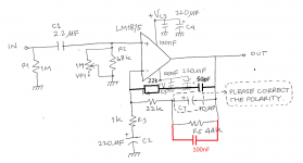
that polar electro with the +ve to the left suits a BJT input stage that has PNP transistors for the LTP.
For NPN LTP the polar electro needs to reversed.
But consider using the back to back instead.
An inverse series connected pair of 10uF+10uF equals an effective 5uF that is resistant to AC voltage.
Or a parallel pair of 10uF+10uF for a final effective value, using 4 capacitors, of 10uF.
BTW.
that polar electro with the +ve to the left suits a BJT input stage that has PNP transistors for the LTP.
For NPN LTP the polar electro needs to reversed.
But consider using the back to back instead.
That's cool! What component values and locale did you use for the zobel?Thanks Daniel. I'll check that later with a toroidal transformer of similar voltage rating.
And I am happy to report schematic of post 510 works well as expected with better bass response. A zobel network is a must which was not there in the schematic.
Cheers!
plgsekip, you can use the RC calculator at my startfetch.com RC Calculator by firstly putting in the component values for an RC that worked but wasn't strong enough, such as that 10R-10n example, and then write down the frequency and proceed with increasing the load, involving a smaller resistor value, while maintaining the same frequency. This comment assumes that it was the frequency you liked, but the load was too tiny for effectiveness. That is likely the case with the very small value examples.
For example, 4.7R with 22n pulls a lot more current than 10R with 10n, although the RC frequency is quite similar.
Likewise, if you've altered the voltage of your amplifier so as to produce 400% wattage, then could be reasonable to assume that many of the resistor figures will have to be current adjusted to compensate for that rather astonishing (and potentially destructive) difference of scale. That 20-0-20 transformer voltage is a bit too high.
Hi Mark,
Regarding post 630, thanks, i'll explore it later.
Hi Daniel,
Thanks for sharing the link in post 633
I am currently comparing PSU of 3x4700 uF per rail of elcos with 2200 uF. I am planning to increase to 2x2200 uF until I find the sound I like. It seems affect the bass and resolution (or detail?). The rail voltage is +/-23vdc (depending the ac mains voltage the resulted dc rail is 22 to 24 vdc).
Last edited:
That has ineffectively little to do with the power supply and a lot more to do with the decoupling. I think that you've found the reason for my series diodes that serve to more certainly define the difference between decoupling capacitance versus reservoir capacitance roles.I am currently comparing PSU of 3x4700 uF per rail of elcos with 2200 uF. I am planning to increase to 2x2200 uF until I find the sound I like. It seems affect the bass and resolution (or detail?). The rail voltage is +/-23vdc (depending the ac mains voltage the resulted dc rail is 22 to 24 vdc).
For my own LM1875 amplifier, I discovered that multiple 2200uF was more practically satisfying than 4700uF capacitors, and I've absolutely no idea why that is. I'm just saying that if that was your impression as well, then you're not the only one to have imagined it.
As diversion/digression Inspired by this thread though.
I was just now perusing the Fleabay/Ali Express Jungle..
intrigued by the wee XY Lm1875 and LM3886 Diy Kits.at 4$ and 6$ each respectively ? Seemed as silly cheap ?.
Subsequently went to Mouser and found 1875 chips are ~4$ and 3886 are ~10$.
Suggesting that our Chinee Friends are erm.. Making their Own Chips.. still.
Does make one wonder about those singing the praises of their diy 'kit' assemblies.. fitted with clone bits.
Inspired by this thread though.I was just now perusing the Fleabay/Ali Express Jungle..
intrigued by the wee XY Lm1875 and LM3886 Diy Kits.at 4$ and 6$ each respectively ? Seemed as silly cheap ?.
Subsequently went to Mouser and found 1875 chips are ~4$ and 3886 are ~10$.
Suggesting that our Chinee Friends are erm.. Making their Own Chips.. still.
Does make one wonder about those singing the praises of their diy 'kit' assemblies.. fitted with clone bits.
Sighh.. It's looking to be a long wet winter, I'm in need of a small project.
Was thinking this wee 1875 build could be entertaining.
And I would like a small Bedroom setup.
I have had a 'few' Ta2020 attempts.
Reasonable sounds (finally
Still, I would prefer improvement, if possible.
Tried a 3116 Fleabay board, Awfull is the Honest descriptor.. it's for the Bin.
I have a Akitika lm3886 and given it's cost, It's quite good actually.
Far better than my paired Arcam amps..were.. grrr.
Soo gentlemen, What quality level could I reasonably expect from a 1875 diy?
You can cause an LM1875 to imitate just about any other amplifier. So, you're not stuck with just one sound.
Because of output power, it will do best in smaller rooms, or even a "parlor"; but, it is not likely to do very well in a modern "great room" (house with almost no doors) or barn.
Because of output power, it will do best in smaller rooms, or even a "parlor"; but, it is not likely to do very well in a modern "great room" (house with almost no doors) or barn.
- Home
- Amplifiers
- Chip Amps
- Beginner's Gainclone, HiFi LM1875, The Amplifier Board