You can make an LM1875 imitate just about any other amplifier and LM1875 has lower noise, which roughly equates to higher resolution.danielwritesbac: you've built an amp based on the TDA7297, so, in your opinion which sounds better [yeah, yeah I know it's subjective, but still...]? One of these [in this thread] LM1875 implementations or the one you built based on the TDA7297? I'm looking to build a low part P2P amp which is a step up from the TDA7297.
That's definitely a step up.
However, probably not on the datasheet sample schematic (except for when under-volted, which is how you get that datasheet example to work practically--this involves a 12,0,12vac center tap transformer and results in an 8W~9W amplifier).
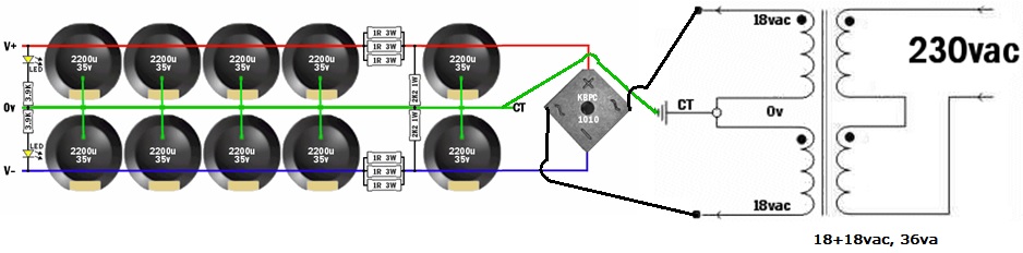
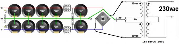
The TurboII schematic works well and at 22W, but if you use voltage lower than printed, you'd need to alter the gain divider a little (lower values go with lower voltage). I seemed to have missed the middle ground entirely. If you do use the voltage printed, you'd need two of 1 ampere 18,0,18vac, 36va center tap transformers, because it has to be a monobloc build (the transformer serves double-duty as current limiter for protection). Thereby, the voltage printed is not actually used except to handle momentary peaks, and music does have a lot of that.
I also like the TDA7293 so long as it is on the very smallest size board available. It offers very similar performance and TDA7293 can use a very very wide range of voltage, so that transformer shopping is easier. In that case, the datasheet sample schematic is so bad that explosions and overheating are commonplace; however, I do have a TDA7293 schematic that works very nicely indeed--just swap a few resistors and caps and get a very nice amp. After the changes, the inbuilt protection works faithfully, so it can be a stereo build, involving one nice big 22+22vac dualie (or 22,0,22vac center tap) transformer with at least 8 amperes (at least 350va).
The TDA7297 with Trileru's board should work fairly well if all four power caps are 680uF (470 was too small except for use with the TV when you want the voice band louder, and 1000 was too large because a little muffled, so 680u it is). That particular board (a huge step-up in audio quality) and 13.5vdc or so, gives you a much easier time building an amplifier.
Summary:
The highest resolution on this list, is the LM1875, and there are many different ways to use it.
The most concert-like sound is provided by the TDA7293, after some fair modding.
The easiest to build and least expensive amplifier is the TDA7297.
hi Daniel, newbie here just finished building my first LM1875 chipamp
is there any room for improvement here?
or did i do something wrong?
i use 20-0-20 vac transformer (it's 20.58 precisely), i yanked this from an old Aiwa mini compo, i believe it's made by Bando
i live in Indonesia which use 220 Volts mains
big thanks for any kind of response from anyone
i'm not a native speaker so please bear with me")
is there any room for improvement here?
or did i do something wrong?
i use 20-0-20 vac transformer (it's 20.58 precisely), i yanked this from an old Aiwa mini compo, i believe it's made by Bando
i live in Indonesia which use 220 Volts mains
big thanks for any kind of response from anyone
i'm not a native speaker so please bear with me
Attachments
What is the DC voltage of the rails (output of your power supply)?hi Daniel, newbie here just finished building my first LM1875 chipamp
is there any room for improvement here?
or did i do something wrong?
i use 20-0-20 vac transformer (it's 20.58 precisely), i yanked this from an old Aiwa mini compo, i believe it's made by Bando
i live in Indonesia which use 220 Volts mains
big thanks for any kind of response from anyone
i'm not a native speaker so please bear with me
What is the amperage or va of your transformer?
add an input RF filter.hi Daniel, newbie here just finished building my first LM1875 chipamp
is there any room for improvement here?
or did i do something wrong?
i use 20-0-20 vac transformer (it's 20.58 precisely), i yanked this from an old Aiwa mini compo, i believe it's made by Bando
i live in Indonesia which use 220 Volts mains
big thanks for any kind of response from anyone
i'm not a native speaker so please bear with me
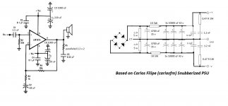
Move the PSU snubber to the transformer secondaries.
Thanks! Daniel. So the latest Turbo II schematic is what is linked in your signature, right? This?:
And should I use this as the PS for each mono block? Please suggest better or improvements because after all, an amplifier is only as good as its power supply. Or should I build this [https://www.quasarelectronics.co.uk/kit-files/smart-kit/1217.pdf] P2P?
BOM for amp board. Can I request someone to check this for me once and point out mistakes if any? I intend purchasing the components tomorrow.
Resistors [1W, carbon]:
Capacitors:
Diodes:
IC:
Heatsink
TO-220 washer
Screw - 3x12mm
Nut - 3mm
Washer - 3mm
Terminals:
Everyone, please feel free to chime in with your thoughts on which PS I should use
And should I use this as the PS for each mono block? Please suggest better or improvements because after all, an amplifier is only as good as its power supply. Or should I build this [https://www.quasarelectronics.co.uk/kit-files/smart-kit/1217.pdf] P2P?
BOM for amp board. Can I request someone to check this for me once and point out mistakes if any? I intend purchasing the components tomorrow.
Resistors [1W, carbon]:
R1 - 1M
R2 - 22K
R3 - 2.7K
R4 - 2.2Ω
R3 - 100K
R4 - 5.6Ω
R2 - 22K
R3 - 2.7K
R4 - 2.2Ω
R3 - 100K
R4 - 5.6Ω
Capacitors:
C1 - 2.2μF poly
C2 - 220pF
C3 - 100μF 63V Electrolytic
C4, C5 - 100nF Ceramic
C5, C6, C7, C8 - 220μF 50V/63V Electrolytic
C9 - 47nF
C2 - 220pF
C3 - 100μF 63V Electrolytic
C4, C5 - 100nF Ceramic
C5, C6, C7, C8 - 220μF 50V/63V Electrolytic
C9 - 47nF
Diodes:
D1, D2 - 1N5406
IC:
LM1875T
Heatsink
TO-220 washer
Screw - 3x12mm
Nut - 3mm
Washer - 3mm
Terminals:
2 PIN 5mm TERMINAL x 2
3 PIN 5mm TERMINAL
3 PIN 5mm TERMINAL
Everyone, please feel free to chime in with your thoughts on which PS I should use
Attachments
Last edited:
Change the carbon resistors to metal film <=100ppm/C 1% tolerance.
Starting from the left.
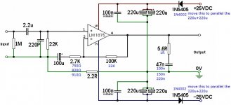
1M ok, 2u2 ok, 220p ok, 22k ok, 100u ok, 2k7 becomes 750 or 820 or 910 depending on what gain you need, 2r2 might be OK, maybe a bit higher for a stereo build and needing to attenuate interference current.100k becomes 22k to match the input for lowest DC output offset, two 100nF ok, four220uF ok, or two 470uF or two 1mF, 1n5405, change to 1n4002 or higher and move the diodes to parallel the decoupling caps. These will then prevent significant reverse voltage on the caps if a fault develops and if you make a mistake with the PSU, these will blow the close rated mains fuse at start up, 5r6 becomes 1r and 47n becomes 100n or 150n or 220n
I don't know where you got that sch from but it is rubbish.
Starting from the left.
1M ok, 2u2 ok, 220p ok, 22k ok, 100u ok, 2k7 becomes 750 or 820 or 910 depending on what gain you need, 2r2 might be OK, maybe a bit higher for a stereo build and needing to attenuate interference current.100k becomes 22k to match the input for lowest DC output offset, two 100nF ok, four220uF ok, or two 470uF or two 1mF, 1n5405, change to 1n4002 or higher and move the diodes to parallel the decoupling caps. These will then prevent significant reverse voltage on the caps if a fault develops and if you make a mistake with the PSU, these will blow the close rated mains fuse at start up, 5r6 becomes 1r and 47n becomes 100n or 150n or 220n
I don't know where you got that sch from but it is rubbish.
post586 amp sch is rubbish.
That's the one immediately before my reply explaining what to keep and what to change.
Needing 7 changed component values cannot be good!
Oh and it needs a defined source impedance to get the RF attenuator working within a defined range.
That's the one immediately before my reply explaining what to keep and what to change.
Needing 7 changed component values cannot be good!
Oh and it needs a defined source impedance to get the RF attenuator working within a defined range.
Last edited:
OK, read my post 580 and Daniel's response to that in 581. In that he recommends building the Turbo II version of his take on this amp. The Turbo II schematics are in Daniels signature which is what I linked to.post586 amp sch is rubbish.
Is that the only reason for you saying it is rubbish? If yes, then with the changed values that you provided, does it cease to be rubbish? If EVEN with the changed values that you provided, it still remains rubbish then you should not leave it at that. I suggest you spell out why exactly it is rubbish and give Daniel a chance to explain why he used what he used and where he used it. Maybe you can post a schematic that according to you is not rubbish and once everyone agrees that it is the bees knees, I'll build that instead of Daniel's schematic.Needing 7 changed component values cannot be good!
That's fine - I can always change that later. No big deal.Oh and it needs a defined source impedance to get the RF attenuator working within a defined range.
Last edited:
OK, so can you [or anyone else] please suggest a schematic which I should build that is not rubbish? I'll build that instead.Daniel won't listen.
But he is improving and gradually adopting science as the basis of electric current flow.
OK, will do. Thanks!Do those 7 changes to get it working properly.
The two input filters will define the amplifier passband.
You select component values that ensure the amplifier works properly within that passband.
Then you select feedback values to give the gain you require AND give zero output offset.
and finally you follow the manufacturers advice on supply rail decoupling and output loading to give stabilitiy.
Only when someone has produced evidence that the manufacturer has got the stability components wrong do you change them for the better.
I am very suspicious about the 1r0 for the output Zobel, but my suspicions are worth nought because I have not seen any evidence that it should be different, or will be more stable.
I do advise you fit the other half of the Thiele Network to make the amplifier more tolerant of reactive loadings. Try ~1uH in parallel to ~3r3 to feed the output terminal and at the output terminal, add in a snubber R+C of 10r+100nF. This attenuates RF interference that tries to get back into the NFB route to get amplified at the -IN pin.
Where is the 1r0? There is a 5.6R+47n as a Zobel.I am very suspicious about the 1r0 for the output Zobel, but my suspicions are worth nought because I have not seen any evidence that it should be different, or will be more stable.
There is no Thiele network. AFAIK, an LR combination is a Thiele network, so what is this other half that you are referring to?I do advise you fit the other half of the Thiele Network to make the amplifier more tolerant of reactive loadings. Try ~1uH in parallel to ~3r3 to feed the output terminal and at the output terminal, add in a snubber R+C of 10r+100nF. This attenuates RF interference that tries to get back into the NFB route to get amplified at the -IN pin.
I think I now understand what you are telling me. Correct me if I'm wrong and let me know if I'm right:I do advise you fit the other half of the Thiele Network to make the amplifier more tolerant of reactive loadings. Try ~1uH in parallel to ~3r3 to feed the output terminal and at the output terminal, add in a snubber R+C of 10r+100nF. This attenuates RF interference that tries to get back into the NFB route to get amplified at the -IN pin.
1. Ditch the current zobel values and instead use 10Ω+100nF as the zobel [snubber] values.
2. Put in a Thiele network of 1uH with 3.3Ω.
Last edited:
not quite.
The Thiele Network is a combination of R+C from output to ground and an L||R from output to load.
The R+C is a Zobel but is only half of the Thiele Network. It needs the L||R to complete this.
The 1875 datasheet shows the 1r0+C for the Zobel, I did not read the notes, to see if they mention the L||R. Most amplifiers benefit in improved stability by fitting the Thiele Network.
The final 10r+100nF is an extra to help with RF attenuation of interference being picked up by the speaker cables and being injected into the -IN pin to be amplified.
- Home
- Amplifiers
- Chip Amps
- Beginner's Gainclone, HiFi LM1875, The Amplifier Board