Vic,
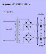
It is basically a standard power amp ps without "any" inductance/resistance in series (see picture).
You would need a transformer with 2x18 volt rating at max. power. This would probably give you around 19.5 ac volts with a light load (max. power and light load depends on your average listening levels and power amp design)
After the rectifiers and caps you should have a dc level in the area of 27.5 vdc. This will work well for maintenance charge of 2 series 12 volt lead acid batteries.
If cost is not a big issue I would recommend that you build the ps/charge unit to run the power amp without batteries and then just create a "battery switch on and charge circuit"
This way you can choose how you want to run and be sure you have enough voltage and current to support both maintenance charge and running the amp (there is very little difference between charge on and off)
The biggest issue for me was to start it up on batteries, the series resistance is VERY low compared to a transformer. Which when you switch on and have a big capacitor bank will create completly crazy start up currents.
You could build a soft start circuit or just use the charge unit to fire up the caps and then switch on the batteries.
Hope it helps!
Attachments
Verbal said:
We may not be asking them, but they'll do anyway(it's not a constant 24V BTW, but will start at about 26V when fully charged and go down to ca. 22V when you should switch them off)
I am sorry.What I meant was they will not be outputting 24v always into the same load.
Yes, however, to stay with the example of 4 12V/7Ah batteries to get +/-24V, the total is still 7Ah, as they're all in series.
Yes the impression is they are connected in series , but this is misleading I think.Correct me if I am wrong but since we are talking about two +- rails and an AC signal doesn't it mean that both rails will never be under the same load at exactly the same time ? So in fact the current consumption is shared over time between the two rails. This means that for a 1amp average circuit half the time the current will be supplied by one rail and the other half by the other rail. So over one hour the consumption will not be 1ah per rail but 1/2ah per rail. In effect you have to add the two rails AH in this type of circuit.
I could be wrong of course because I have only started informing myself on electronics 12 months ago.
protos said:
Yes the impression is they are connected in series , but this is misleading I think.Correct me if I am wrong but since we are talking about two +- rails and an AC signal doesn't it mean that both rails will never be under the same load at exactly the same time ? So in fact the current consumption is shared over time between the two rails. This means that for a 1amp average circuit half the time the current will be supplied by one rail and the other half by the other rail. So over one hour the consumption will not be 1ah per rail but 1/2ah per rail. In effect you have to add the two rails AH in this type of circuit.
I could be wrong of course because I have only started informing myself on electronics 12 months ago.
Before I comment on this quote, I think we should clear up some terminology:
We're talking about two different things here. One is the capacity of the battery bank, and the other is the runtime of the load. These are of course related, but we shouldn't think of the capacity of the battery bank in terms of the current draw of the load. The capacity of the battery bank is a constant. The current draw of the load, and the runtime of the load, are the variable parameters.
In the original example of four 12V, 7Ah batteries connected in series to form +/- 24V supplies, the total capacity of this battery bank is 7Ah. It can supply 48V at 7A for one hour (in theory), for a total energy capacity of 336Wh. Or, looked at another way, the positive and negative supplies have a total energy capacity of 168Wh each. This energy capacity is constant, regardless of the load.
Consider a DC load that requires 1W of power, and an AC load that requires the same, 1W RMS.
The AC load is swinging between +24V and -24V, drawing 1W RMS from the positive supply half the time, and 1W RMS from the negative supply half the time. Each of these supplies have a total capacity of 168Wh, so the load can run for 2 x 168 = 336 hours.
The DC load is drawing 1W constantly, across the complete supply (48V). The complete supply has a capacity of 336Wh, so this load too can run for 336 hours.
So the runtime is not doubled for an AC load. The battery bank has a given, fixed capacity, and the average RMS current draw of the load will determine the runtime.
In the real-world case of an amp running at reasonable volume with reasonably efficient speakers, playing music rather than a sine wave, the average RMS current is likely going to be quite low, and the runtime reasonable. Keep in mind that, if you want your batteries to last for years, you shouldn't be going much deeper than 20% depth of discharge. For the battery bank discussed above, that means not using more than 67 Wh between charges.
Re: Sparhawk
You can buy watt-hour meters. They are often used with renewable energy systems and electric vehicles, to monitor battery status. Otherwise, you would have to keep track of the average current over time, and calculate it.
ralf said:..how can i see, when 67wh are used, and i should reload the batteries?
Only with calculating?
Or is the ability to show it with any circuits?
greets,
Ralf
You can buy watt-hour meters. They are often used with renewable energy systems and electric vehicles, to monitor battery status. Otherwise, you would have to keep track of the average current over time, and calculate it.
Sparhawk said:
The AC load is swinging between +24V and -24V, drawing 1W RMS from the positive supply half the time, and 1W RMS from the negative supply half the time. Each of these supplies have a total capacity of 168Wh, so the load can run for 2 x 168 = 336 hours.
The DC load is drawing 1W constantly, across the complete supply (48V). The complete supply has a capacity of 336Wh, so this load too can run for 336 hours.
.
I agree. The best way to see if your battery supply will be enough is to calculate the W/h because the A/h may cause some confusion. In our case it means you can play one channel at 336W total consumption for one hour. Now I don't know the efficiency of the circuit but in a Btype amplifier it should be quite good.Maybe 60-70%?
Re: Sparhawk
You can also roughly estimate the charging status of the battery from the voltage. It's not very accurate, but should be ok for this purpose.ralf said:..how can i see, when 67wh are used, and i should reload the batteries?
Only with calculating?
Or is the ability to show it with any circuits?
greets,
Ralf
Re: Re: Sparhawk
This is difficult to do accurately, because the voltage vs. state of charge is not linear, and varies with temperature and battery construction. Battery manufacturers should have graphs available showing various voltage vs. state of charge graphs at various temperatures, but these are often hard to find.
You can make some generalizations for a specific battery type (ie, sealed lead acid) at a specific temperature. Most automatic battery chargers work this way. But it is not very accurate. Good battery chargers, or charge controllers (used in solar and wind applications) will have a temperature sensor that is attached to the battery to increase accuracy.
Verbal said:
You can also roughly estimate the charging status of the battery from the voltage. It's not very accurate, but should be ok for this purpose.
This is difficult to do accurately, because the voltage vs. state of charge is not linear, and varies with temperature and battery construction. Battery manufacturers should have graphs available showing various voltage vs. state of charge graphs at various temperatures, but these are often hard to find.
You can make some generalizations for a specific battery type (ie, sealed lead acid) at a specific temperature. Most automatic battery chargers work this way. But it is not very accurate. Good battery chargers, or charge controllers (used in solar and wind applications) will have a temperature sensor that is attached to the battery to increase accuracy.
Re: Re: Re: Sparhawk
This is all correct (and that's why I said 'roughly estimate'). But we can assume that Ralf knows what batteries he's using, and that the temperature in his living room won't be that variable (say somewhere between 20deg and 30deg C in the summer). If you just want to know when it's time for a recharge, you don't really need too much accuracy, do you? So that method shouldn't be that bad...Sparhawk said:This is difficult to do accurately, because the voltage vs. state of charge is not linear, and varies with temperature and battery construction. Battery manufacturers should have graphs available showing various voltage vs. state of charge graphs at various temperatures, but these are often hard to find.
You can make some generalizations for a specific battery type (ie, sealed lead acid) at a specific temperature.
Re: Re: Re: Re: Sparhawk
It can be a viable method; I just wanted to point out that it is difficult to determine the voltage that corresponds to, say, 20% depth of discharge. If you have the graphs, it is no problem. Otherwise, it involves a lot of guesswork.
Verbal said:
This is all correct (and that's why I said 'roughly estimate'). But we can assume that Ralf knows what batteries he's using, and that the temperature in his living room won't be that variable (say somewhere between 20deg and 30deg C in the summer). If you just want to know when it's time for a recharge, you don't really need too much accuracy, do you? So that method shouldn't be that bad...
It can be a viable method; I just wanted to point out that it is difficult to determine the voltage that corresponds to, say, 20% depth of discharge. If you have the graphs, it is no problem. Otherwise, it involves a lot of guesswork.
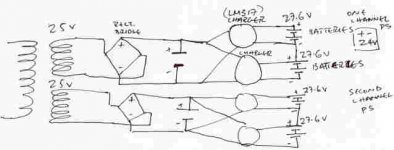
Protos.....the circuit you have drawn will work except that you need power resistors on the output of the regulators for 2 reasons.....one to set the charging current and second to equalize it or one battery might try to draw more.
Another suggestion to the charger is to have some relays on the outputs that open when the batteries are in use so you dont have any AC line noise.
Cheers!!The DIRT®
Another suggestion to the charger is to have some relays on the outputs that open when the batteries are in use so you dont have any AC line noise.
Cheers!!The DIRT®
Protos, that won't work. You can't put the charger circuits in series like that when they're run from the same supply. Take a closer look and you'll see that the midpoint between the batteries and the neg terminal of the lower battery are at about the same potential.
The charger circuit he intends to use does limit current, no need for resistors.JOE DIRT® said:Protos.....the circuit you have drawn will work except that you need power resistors on the output of the regulators for 2 reasons.....one to set the charging current and second to equalize it or one battery might try to draw more.
What about this?
An externally hosted image should be here but it was not working when we last tested it.
Verbal
Are you saying that I need to switch out the series connection between the batteries when I charge them?Your schematic implies this.Of course this greatly increases the complexity of the charger.I would need two extra switches every time I wanted to charge the batteries.Isn't there a simpler way with direct charging of the battery pack as it is connected?What if the second leg charger is the neg type?
Are you saying that I need to switch out the series connection between the batteries when I charge them?Your schematic implies this.Of course this greatly increases the complexity of the charger.I would need two extra switches every time I wanted to charge the batteries.Isn't there a simpler way with direct charging of the battery pack as it is connected?What if the second leg charger is the neg type?
Would need a symmetric supply...Perhaps like this?
An externally hosted image should be here but it was not working when we last tested it.
Hi, Verbal
I think that your first schematic is much better solution. Using relays is good idea because you can isolate power amp from power supply when listen. All time connected charger (in symmetrical schematic) will charge batteries ("and power amp") when you listen music and can put RF noise in system and degrade sound. And, I am not sure that symmetrical charger (your second schematic) will work correctly. Current limiter will "eat" voltage on himself and then voltage limiter will be in improper condition (Vi-Vout must be minimum 3V). I am not sure...IMHO
regards
moamps said:Using relays is good idea because you can isolate power amp from power supply when listen. All time connected charger (in symmetrical schematic) will charge batteries ("and power amp") when you listen music and can put RF noise in system and degrade sound.
I don't see the problem, just turn the charger off for listening...
Current limiter will "eat" voltage on himself
Yes, about 2V or so, depends on the current. No problem if there's enough voltage from the raw supply.
and then voltage limiter will be in improper condition (Vi-Vout must be minimum 3V).
Well, in this case it just passes on V(in) minus the dropout voltage - it won't be able to regulate anything, but then it also doesn't need to as the second regulator takes over at this point. I've been using a pair of 317s in this combination for a while now, works perfectly.
- Status
- This old topic is closed. If you want to reopen this topic, contact a moderator using the "Report Post" button.
- Home
- Amplifiers
- Chip Amps
- Battery-powered supplies