Yes! Fairly, sorta, kinda, sinusoidal. You have to expect such language when dealing with non-linear thinking people like me. ")
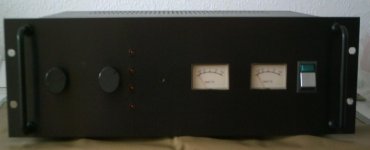
As far as what measures Yamaha took to prevent some LED head from burning up his amp and speakers is hard to tell. The only schematic I have is off a low resolution (fuzzy) PDF file, which I had to split into 4 images (below).
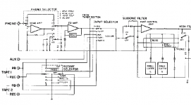
On the 1st image you can see some capacitors & resistors between the volume pot and the "tone control amp" that can be switched in or out of operation using a button the front panel. Yamaha calls this a "sub-sonic filter" for reducing "ultra low frequencies ..... caused from rumble or warped records....such signals can sap vital power and even harm speakers if not attenuated".
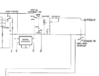
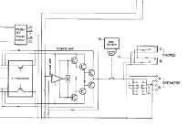
On the 4th image you can see the power amp section (which gets its signal from the pre-amp final output shown in image number 2). I don't see any DC blocking capacitors here.
Oh well. The tests must go on.
By for now.
As far as what measures Yamaha took to prevent some LED head from burning up his amp and speakers is hard to tell. The only schematic I have is off a low resolution (fuzzy) PDF file, which I had to split into 4 images (below).
On the 1st image you can see some capacitors & resistors between the volume pot and the "tone control amp" that can be switched in or out of operation using a button the front panel. Yamaha calls this a "sub-sonic filter" for reducing "ultra low frequencies ..... caused from rumble or warped records....such signals can sap vital power and even harm speakers if not attenuated".
On the 4th image you can see the power amp section (which gets its signal from the pre-amp final output shown in image number 2). I don't see any DC blocking capacitors here.
Oh well. The tests must go on.
By for now.
Attachments
I just had a quick search for your amp but didn't turn anything up.
The above piccys are just basic block diagrams... I wouldn't read too much into whether it has any caps or not from that.
For example the power amp shows the input and feedback loop to be DC coupled (can you see how it is basically an "opamp" with power transistors added) and that would be really unusual to say the least. The feedback return is always (99.999% of time) AC coupled to reduce the gain to unity or 1 at DC. The input is almost always AC coupled... an more so on something where they invite connection to unknown equipment.
I'm sure it will be AC coupled.
It's normal to show the filter caps etc as they have done (rumble etc) but that's about all.
Think that's me done for tonight...
Are you thinking of making a complete amp maybe/perhaps/sometime ish.
There's nothing like hearing your first creation actually driving speakers etc... and then it never ends.
Are you thinking of making a complete amp maybe/perhaps/sometime ish.
There's nothing like hearing your first creation actually driving speakers etc... and then it never ends.
Maybe, perhaps, sometime-ish. Sure! Why not?
Nothing too fancy though. My oldest daughter graduated from college and has her own place now, but has little in the way of anything decent to enjoy her (digital) music collection on. So maybe one the small "chipamp" designs found here a DiyAudio, along with the little preamp your helping me with, might make a nice gift.
Thank you soooo much!
Last edited:
A small chip amp would make a good project as it includes power supplies etc and learning about correct wiring (grounding) techniques.
Get a nice case etc and you could make a small integrated amp
Ok. So if this integrated amp could support three(3) sources, where Source #1 is a line level device (like a CD player), Source #2 is another line level device (like a TV set) and Source #3 is and MP3 player that needs a preamp to boost it's output up to line level strength, would the circuit topology look something like this?:
Source 1 ---------------------> selector switch --|
Source 2 ---------------------> selector switch --|----> Vol. pot----> Power Amp
Source 3 ---> Preamp ----> selector switch --|
Best regards,
Obe1
It would
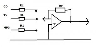
Now you could use an opamp (inverting mode) and have the "input resistor" a different value for each source so as to "equalise" volume levels.
Like this, post #2
http://www.diyaudio.com/forums/solid-state/119151-my-mosfet-amplifier-designed-music.html
the second OpAmp restores absolute phase. There is a lot of debate whether absolute phase matters at all... you can experiment by just swapping both speaker lead polaritys over and see if you can tell a difference. Something I have never tried tbh.
That's "gotcha" hasn't it
The amps here starting post #283
http://www.diyaudio.com/forums/solid-state/96192-post-your-solid-state-pics-here-15.html
It's what I'm sat in front of now
The amps here starting post #283
http://www.diyaudio.com/forums/solid-state/96192-post-your-solid-state-pics-here-15.html
It's what I'm sat in front of now
It would
Now you could use an opamp (inverting mode) and have the "input resistor" a different value for each source so as to "equalise" volume levels.
Like this, post #2
http://www.diyaudio.com/forums/solid-state/119151-my-mosfet-amplifier-designed-music.html
the second OpAmp restores absolute phase. There is a lot of debate whether absolute phase matters at all... you can experiment by just swapping both speaker lead polaritys over and see if you can tell a difference. Something I have never tried tbh.
Well that's very cool. I was struggling with how to switch sources without resorting to power sucking relays. With separate op-amps per source, I wonder if source selection could be accomplished just switching power on & off to the opamp alone.
I need to read the rest of that thread as it's a long one.
Take care!
Hi Obe1,
It's one opamp and as many inputs as you want.
It's a "virtual earth" mixer configuration.
You have each input going to it's own "R1" and then to the switch. Each input goes to a different pole on the switch. The wiper of the switch goes to the opamp... easy.
You select each "R1" to give the same volume for each source. It the classic inverting amp, gain being RF/R1.
It's one opamp
and as many inputs as you want.It's a "virtual earth" mixer configuration.
You have each input going to it's own "R1" and then to the switch. Each input goes to a different pole on the switch. The wiper of the switch goes to the opamp... easy.
You select each "R1" to give the same volume for each source. It the classic inverting amp, gain being RF/R1.
Attachments
Mooly,
Your amplifier is just exquisite!
Thank you. It's all the casework and metal work that I don't like doing.

Hi Obe1,
It's one opamp
It's a "virtual earth" mixer configuration.
You have each input going to it's own "R1" and then to the switch. Each input goes to a different pole on the switch. The wiper of the switch goes to the opamp... easy.
You select each "R1" to give the same volume for each source. It the classic inverting amp, gain being RF/R1.
Ahhhh! Now I get it. Very clever.

Source 1 ---------------------> selector switch --|
Source 2 ---------------------> selector switch --|----> Vol. pot----> Power Amp
Source 3 ---> Preamp ----> selector switch --|
Source 1 ---------------------->selector switch --|
Source 2 ---------------------->selector switch --|-->Vol. pot-->inverting unity gain buffer>--------> Power Amp
Source 3 -->inverting Preamp -->selector switch --|
Adding the extra inverting opamp after the volume pot allows your pre-amp to drive interconnect cables and any sensible power amp input impedance.
Hi,
need to add that the last opamp can be made switchable phase, inverting/non-inverting with just a single pole single way and two extra resistors.
Indeed it can.
I wonder, have you ever done any serious listening regarding absolute phase Andrew ? Must admit I never have.
Source 1 ---------------------->selector switch --|
Source 2 ---------------------->selector switch --|-->Vol. pot-->inverting unity gain buffer>--------> Power Amp
Source 3 -->inverting Preamp -->selector switch --|
Adding the extra inverting opamp after the volume pot allows your pre-amp to drive interconnect cables and any sensible power amp input impedance.
Hello Andrew,
Thanks! I'm game for trying this. For the sake of simplicity, should I use a coupling capacitor between the stages? And if so, would the cap go before or after the volume pot?
Best regards,
Obe1
the inputs to the selector switch can be labeled with the voltage sensitivity to drive the Power amp to clipping.
If the power amp has 20Vac maximum output and a gain of 30 then both input 1 and input 2 are labeled, 660mVac.
If the gain of the input 3 pre-amp is 2times (+6dB) then label 3 is 330mVac.
This third input could go to a second selector switch with different input resistors (or a switchable parallel resistor) to give alternative sensitivities.
I would have a DC coupled output to the RCA socket and a second parallel route through a 10uF polypropylene audio cap to the AC coupled output RCA. Add a 1M5 or 2M2 after the cap to discharge any static build up on the AC output pin.
I have not tried evaluating absolute phase.
Last edited:
Obe1,
Volume controls should always be AC coupled as a general rule. That means a cap feeding the signal to the "top end" of the pot and another connected to the wiper (output of pot).
The reason why is any DC at all (even a millivolt or two) makes the pot "noisy" as you turn it.
Caps get a lot of bad press, usually undeserved.
- Status
- This old topic is closed. If you want to reopen this topic, contact a moderator using the "Report Post" button.
- Home
- Source & Line
- Analog Line Level
- Basic Common Emitter Amp Help