")
I live about 50 miles from the nearest machine shop, buy the time I factor in gas prices to and from plus labor I get this $$$$. I just ordered this table-saw blade > Oshlun #SBNF-100100 , It is a 100 tooth TCG made just for Aluminum ! I hope it cuts clean with-out to much De-burring needed. Also the blade may pay for it-self over time, and still is cheaper than going to the machine shop. Could someone recommend a good cutting oil to use with it ? Thanks
Last edited:
Could someone recommend a good cutting oil to use with it ?
Lenox lube tube. It's waxy and sticks to your metal or blade, keeps oil from spraying all over.
Did boards for this amp ever get created? A they still available?
If yes, a link to them would be great!
Thanks in advance.
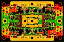
Yes I had a few F5TBS-v.1.1 boards built. The image below shows the artwork. The board has numerous options:
- One Balanced F5 (with or without turbo diodes)
- A pair of unbalanced F5 channels (with or without turbo diodes)
- A single unbalanced F5 channel with 2 MOSFETS per rail(with or without turbo diodes)
Attachments
I want to buy boards. Do I need to have them made or how do I get some?
Check your private mail.
lhquam, did you ever manage to get round to doing the measurements using 2sk1530 in this setup compared to the FQA/FQPs ?
I have built channels with FQA28N15/FQA36P15 MOSFETs and with FQP19N20C/FQP12P20 MOSFETs. I never did any tests with 2SK1530/2SJ201, but based on my experience with an unbalanced F5, they should be very good.
One thing to consider about the balanced F5. It is not necessary that the NMOS FETSs be well matched to the PMOS FETs, but the FETs and drivers of the same polarity need to be matched to each other.
Of course Papa's P3 adjustment allows the nulling of the 2nd harmonic in the F5 without the need for FET matching.
I cannot explain any better than Pavel Macura already did in 2008 :
Distortion in JFET input stage circuits
"5. Influence of matching of N and P halves in complementary differential pair
...... Distortion rised and we can see also 5th harmonic has appeared....... The reason is different threshold voltage and transconductance of N and P jfets...... We shall try to make the models more similar for both N and P jfet. Now the 5th harmonic disappeared, 3rd is reduced and all 4 drain currents are same.
So, to keep the lowest distortion and avoid higher harmonics, we need to have N and P jfets as equal as possible."
And this is of course referring to a differential pair in balanced mode.
The penalty of N-P mismatch is high order odd harmonics, not 2nd.
Patrick
> It is not necessary that the NMOS FETSs be well matched to the PMOS FETs, but the FETs and drivers of the same polarity need to be matched to each other.
How many orders of harmonics have you taken into account in maiing that statement ?
Patrick
I should have qualified my statement to just 2nd (or even) harmonics. I am just now developing the math and simulations to show the effect on the higher harmonics. Independent feedback loops of the two halves of a balanced amplifier lead to the generation of higher harmonics before cancellation can occur. If each half has high levels of 2nd harmonic, as would be the case with poorly matched PFETs and NFETs, then the feedback loops generate significant higher harmonics. If the two halves are identical then in the balanced output the even harmonics will cancel, but the odd harmonics will add. Therefore I agree that NFETs and PFETs also need to be well matched in order to minimize odd order harmonics.
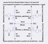
I have crunched equations and run simulations that confirm by previous statement (conjecture) that in the balanced amplifier it may not be important that the PFETs match the NFETs. The simulations are of the output stage only and with no feedback, being driven by perfect sine wave voltage sources. Show below is an extract of the schematic.
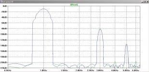
With 2:1 mismatch of the transconductance between the PFETs and NFETs vs. exactly matched, I see only about 4-10% increase in that balanced THD vs. exactly matched FETs, depending on the values of the source degeneration resistors. This includes odd harmonics.
I am trying to decide whether to start a new thread for these results, If not a new thread, what thread should they go in: F5, F6, this thread???
Thanks those are v nice insights - I ran some fets on a tracer and frankly was pretty surprised at how complementary the Toshibas measured.its too bad they are no longer manufactured - It sounds they will indeed make a good fit for the F5 ...
Attachments
But if there IS feedback (like in the balanced f5) then you would see a bigger relative improvement when using matched p and n channel fets correct ? Example above has no feedback ... Or am I missing the point ?
With feedback I do not expect the conclusion to change. To verify this, I plan to run simulations with an F5 and similar variations of FET transconductance.
There are two forms of mismatch -- Vgs and Yfs.
In case of a Yfs only mismatch (i.e. only one coefficient change of the first order in the transfer function), there is no effect in the distortion spectrum, as expected.
It gets complicated when you have a Vgs mismatch, because now you need to change the drain resistor value of the first stage to balance the bias. So the gain of the first stage changes. But since the first stage (and the second stage) are not linear, but have higher order coefficients, you start generating high order terms from low order coefficients, and in doing so, changing the higher order harmonics. Of course in perfectly identical left and right halves (which only exist ion simulations), all even harmonics will cancel. So this only affect the odd order terms
We thought we were clever and could make use of this to lower the odd order harmonics by deliberating shifting the Vgs match. We failed, they always got worse when we shifted from perfect balance. Not much, you can argue, but measurable. The distribution of harmonics changes.
Many have built the F5 with mismatched FETs, as the original Fairchild for example. As long as you like the sound, it is all that matters.
Patrick
Last edited:
I cannot disagree with those remarks. Yes, Vgs differences have a big effect in the F5 because the adjustment of output bias current and offset voltage also affects the loop gains, and therefore the polynomial coefficients and harmonic structure of the combined gain stages. However, beyond the 3rd harmonic these effects are so small as to be virtually unmeasurable.
The main point I am trying to make is that matching NFETs to PFETs is no that important, in the balanced F5 or the unbalanced F5 with the P3 adjustment.
The simulations (and equation crunching) show that minimizing the output FET source resistors is the best way to reduce the 3rd harmonic. Thus, choosing output FETs with small internal Rs and high transconductance, and good thermal coefficient would be a good choice. How about a circlotron using SJEPR100s and no source resistors?
There are two forms of mismatch -- Vgs and Yfs.
In case of a Yfs only mismatch (i.e. only one coefficient change of the first order in the transfer function), there is no effect in the distortion spectrum, as expected.
It gets complicated when you have a Vgs mismatch, because now you need to change the drain resistor value of the first stage to balance the bias. So the gain of the first stage changes. But since the first stage (and the second stage) are not linear, but have higher order coefficients, you start generating high order terms from low order coefficients, and in doing so, changing the higher order harmonics. Of course in perfectly identical left and right halves (which only exist ion simulations), all even harmonics will cancel. So this only affect the odd order terms
We thought we were clever and could make use of this to lower the odd order harmonics by deliberating shifting the Vgs match. We failed, they always got worse when we shifted from perfect balance. Not much, you can argue, but measurable. The distribution of harmonics changes.
Many have built the F5 with mismatched FETs, as the original Fairchild for example. As long as you like the sound, it is all that matters.
Patrick
> However, beyond the 3rd harmonic these effects are so small as to be virtually unmeasurable.
I choose to disagree.
Take a look at the Blowtorch thread and see how John goes about minimising high order harmonics.
The human hearing is not linear and much more sensitive to 4th & above than to 2nd & 3rd.
That is why in the opinion of many, the THD is a poor measure of SQ and that one should use some form of weighted scale.
The unfortunate things is that people have not been able to agree on one.
Also, as I have mentioned before, cancellation between left & right halves in a balanced amp is never 100%.
So if I have to choose between 1-0.9=0.1 and 10-9.9=0.1, I choose the former.
That is why, IMHO, it always pays to reduce the intrinsic distortion in the basic circuit.
And having "perfectly" matched devices is the first step towards that.
But that is only my personal view. There is no universal truth in audio.
Patrick
- Status
- This old topic is closed. If you want to reopen this topic, contact a moderator using the "Report Post" button.
- Home
- Amplifiers
- Pass Labs
- Balanced F5 in a Small Footprint