coolness! i'll keep watching the thread, i'll volunteer to test out the balanced headphone amp version, should be able to get away with passive heatsinking for that with a reasonably small heatsink
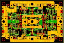
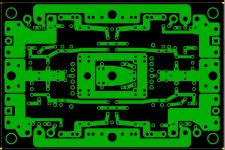
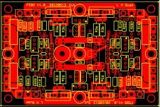
The same card is used for all different configurations. The difference is what components, rail voltages, bias currents, and packaging options are used.
For example, an F5-Turbo-V1 is created by only populating the MOSFET and its gate and source resistors on one of the amplifiers of the board, and (externally) connecting the 2 output standoffs together. Two wire jumpers are needed to connect the gate resistors to the JFET drain node of the other amplifier.
Similarly, the F5-Turbo-V2 is created by implementing the V1 configuration and adding the MUR3020WT diodes.
INteresting build. I have seen the effectiveness of fan cooling in my testing. I can run 2 fans across a 12" heatsink of the 10,08 from heatsink USA and even with 6 fets at 2A bias, cant get the thing to get hot. It is really amazing the amount of heat you can pull off with just that simple concept. May have missed it, but do you try to control heatsink temp at a certain level or do you just set fan to a quiet level and let it be? Consider diode addition. You will be using the fets to their full potential, leaving nothing on the table. Allows reduction of output pair sets.
Last edited:
yeah I know, but it didnt seem you had built the headphone version and I presume possibly dont have any balanced headphones?, I have several.. so I would build and test; thats what I meant
I am not sure how to size the power supply for headphones. What wattage do you think is necessary for your headphones. What impedance?
I'd suggest you aim for 12Vac absolute max for high impedance phones and for absolute max ClassA current of 100mA for lower impedance phones.
If this is set up as a Optimally biased ClassAB amplifier then it can even drive 8ohms phones to low voltages for very High SPL.
The PSU would be +-15Vdc delivering a quiescent current of ~60mA/channel.
Theoretically 7VA 12+12Vac would be sufficient.
I would go for 30vA 15+15Vac and regulate to +-15Vdc.
INteresting build. I have seen the effectiveness of fan cooling in my testing. I can run 2 fans across a 12" heatsink of the 10,08 from heatsink USA and even with 6 fets at 2A bias, cant get the thing to get hot. It is really amazing the amount of heat you can pull off with just that simple concept. May have missed it, but do you try to control heatsink temp at a certain level or do you just set fan to a quiet level and let it be? Consider diode addition. You will be using the fets to their full potential, leaving nothing on the table. Allows reduction of output pair sets.
I have made temperature measurements at different bias currents and estimate a temperature rise of .1 C/W at 1200RPM fan speed (Noctua NF-S12B-FLX Noctua.at - sound-optimised premium components "Designed in Austria"!). At around 500 RPM, I estimate .16C/W), but I haven't made enough measurements at the lower speed to be confident in this number.
V1.1 of the board will support the Turbo diodes.
... May have missed it, but do you try to control heatsink temp at a certain level or do you just set fan to a quiet level and let it be? ...
Currently I run the fan at a constant voltage. I have considered a temperature control servo, but I haven't spent the time to implement it. It is worth considering further.
Compact and well thought off design. Really good job.The following images show amplifier without cover. The dimensions are 11" W x 9" H x 13" D. An alternate chassis design is presented in a later post.

One thing to consider: the whole thermal scheme depends on the fan. I would add a temperature-circuit-breaker that will disconnect the power to toroid's primary winding when temperature on the heatsink reaches 70 degrees Celsius (i.e. when the fan fails).
Compact and well thought off design. Really good job.
One thing to consider: the whole thermal scheme depends on the fan. I would add a temperature-circuit-breaker that will disconnect the power to toroid's primary winding when temperature on the heatsink reaches 70 degrees Celsius (i.e. when the fan fails).
Sharp as a tack as always, Juma
The reason I mention it is that I think Nelson like them to get a little hot. I believe it affects their transconductance. If I am wrong, there are enough smart folks around who will let us know
accent is more on "constant" xconductance , which you're having with constant temp
Compact and well thought off design. Really good job.
One thing to consider: the whole thermal scheme depends on the fan. I would add a temperature-circuit-breaker that will disconnect the power to toroid's primary winding when temperature on the heatsink reaches 70 degrees Celsius (i.e. when the fan fails).
I agree, and in fact have purchased such a circuit breaker. The question is whether there needs to be a relay also so that a manual reset is required to restart the amplifier. There should also be a temperature servo for the fan voltage.
interested
L,
Truly impressed by your efforts. You know already that I am interested in the pcbs , so please let me (us) know if and when they may be available to buy into. THX.
a.) I am also looking forward to your assessment of Toshiba fets (1530/201). Please be objective just like when having compared bal vs. unbal amp. Thx.
b.) I am also looking up to you to evaluate the different grounding schemes for the balanced configuration (I am still (re)considering those only with lower rails at +-15V vs. 2 unbal F5s).
p.s. you'd be suprised how close the physical layout of your amp is to what I had planned for; only mine will take a lot longer since I am busy with other projects and life, hmmmm (but i promise to share it here once materialized).
Cheers.
S.
L,
Truly impressed by your efforts. You know already that I am interested in the pcbs
, so please let me (us) know if and when they may be available to buy into. THX.a.) I am also looking forward to your assessment of Toshiba fets (1530/201). Please be objective just like when having compared bal vs. unbal amp. Thx.
b.) I am also looking up to you to evaluate the different grounding schemes for the balanced configuration (I am still (re)considering those only with lower rails at +-15V vs. 2 unbal F5s).
p.s. you'd be suprised how close the physical layout of your amp is to what I had planned for; only mine will take a lot longer since I am busy with other projects and life, hmmmm
(but i promise to share it here once materialized).Cheers.
S.
L,
Truly impressed by your efforts. You know already that I am interested in the pcbs
a.) I am also looking forward to your assessment of Toshiba fets (1530/201). Please be objective just like when having compared bal vs. unbal amp. Thx.
b.) I am also looking up to you to evaluate the different grounding schemes for the balanced configuration (I am still (re)considering those only with lower rails at +-15V vs. 2 unbal F5s).
p.s. you'd be suprised how close the physical layout of your amp is to what I had planned for; only mine will take a lot longer since I am busy with other projects and life, hmmmm
Cheers.
S.
The availability of the board will depend on demand. There is still a lot or work to be done putting together the documentation for all of the different options that board will support and the BOM for those options. I would be happy if there was enough interest for the DUIAudio Store to accept it.
I still have not built with the Toshiba FETs, largely because I have a shortage of them. I built an "ordinary" stereo F5 using them and it sounds great, but I do not have of them for a balanced pair with these boards.
My grounding scheme was borrowed from EUVL's F5X design. It is as close to a perfect star ground as you can get. My measurements of 60 Hz noise are near the limits of my equipment, and totally inaudible. I really like using standoffs for the power, ground and output output connections. No unsoldering/resoldering needed to swap boards. Easy connections into crowded boards. For the ground, it forms a nearly perfect star ground.
I am not sure how to size the power supply for headphones. What wattage do you think is necessary for your headphones. What impedance?
not a whole lot, generally to cover most headphones including up to 600ohms I would say 2-3W with 12v rails to cover even the most hungry transients. for me less as my highest Z headphones are 300ohms HD600 but I also use some 28ohms monitors, which may not be the best match.
to be clear though, I dont feel the need for that much, but some get a bit crazy with what they want out of a headphone amp these days. I would build for 1-1.5wpc class A
Last edited:
Qusp,
+-12Vdc supply rails sets your limit to ~8Vac into your 300ohm headphones.
That is ~200mW or about +23dBW above the mW sensitivity rating = pretty loud.
For 28ohms headphones with 2W of amplifier drive capability, you need ~10.6Vpk output, OK for +-12Vdc supply.
The current requirement for a 28r resistor load is 375mApk, for 28ohms headphones I would double that to 750mApk.
If a single ended topology then that 750mA becomes the output bias current setting. A far cry from a 2W to 3W ClassA amplifier. That would require 36W of dissipation for two channels.
If a push pull topology then the top end of the current range can be in ClassAB and the bias setting for the output stage can be very much lower may be just 20mA to 100mA depending on heatsinking and devices.
Notice how very different the amplifier requirement for high vs low impedance headphones is.
Last edited:
- Status
- This old topic is closed. If you want to reopen this topic, contact a moderator using the "Report Post" button.
- Home
- Amplifiers
- Pass Labs
- Balanced F5 in a Small Footprint