ok, sounds good.
so on to the next question: i intend to power the B1 with batteries. I thought about 2x9V batteries. Now i read that the rechargeable 9V batteries only supply 8,4V. So two of those would add up to 16,8V instead of the recommended minimum of 18V. Is that likely to cause any problems?
so on to the next question: i intend to power the B1 with batteries. I thought about 2x9V batteries. Now i read that the rechargeable 9V batteries only supply 8,4V. So two of those would add up to 16,8V instead of the recommended minimum of 18V. Is that likely to cause any problems?
Pass DIY Addict
Joined 2000
Paid Member
ok, sounds good.
so on to the next question: i intend to power the B1 with batteries. I thought about 2x9V batteries. Now i read that the rechargeable 9V batteries only supply 8,4V. So two of those would add up to 16,8V instead of the recommended minimum of 18V. Is that likely to cause any problems?
I use 3x 9v batteries , good for around 80 hours , with AC I go with regulator 24/30vdc max
You might want to do a quick search on batteries as a power supply for low-level audio signal circuitry. Batteries of nearly all types tend to throw off a large amount of high frequency noise. It may not matter in this application (I haven't tried)...
i thought the opposite was the case and people value batteries in hifi for steady supply and low noise

Hi Zen,
i am mainly going to use the B1 with A FirstWatt M2 Clone, which has a imput impedance of 100K.
i was also reading ... you are going same direction than Papa, but 22-51R isn't that too low?
B1 Buffer Preamp
Thanks!
I find, and I think I have heard Zenmod also say?, the M2 comes alive with a little gain. Even with my higher efficiency speakers, >100 dB, this is true, and to a greater degree with lesser efficient speakers.
That said, it will sound great within its gain limitations and your listening preferences, room size, etc.
Russellc
The advantage of batteries is the decoupling from the mains. It's free of mains hum and mains harmonic.
I wouldn't worry about HF noise from batteries, try it, if there ends up being an issue, there are other avenues to explore.
I tried batteries, laptop power supply, and as you know, there same regulated power supply you used in this build thread.
I couldn't tell a great deal of difference between the batteries (2 x 9 volt) and the laptop supply. The simple regulated supply you outline in build thread beat them both by a noticeable amount (imho) across the board.
The commercial B1 used a wall wart if I recall without problems.
Russellc
Last edited:
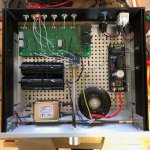
Finally my B1 is up and sounding fantastic! A perfect match for M2 and horn speakers (102dB).
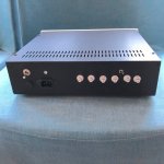
50VA transformer, Salas BiB (19V), B1 PCB from passdiy, chassi from modushop.biz
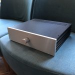
The inside image just lacking cables from the regulator. Front with a not blue led .
50VA transformer, Salas BiB (19V), B1 PCB from passdiy, chassi from modushop.biz
The inside image just lacking cables from the regulator. Front with a not blue led
.Attachments
Finally my B1 is up and sounding fantastic! A perfect match for M2 and horn speakers (102dB).
Nice Mundorf Caps. they are huge!
better to use a 100r resistor plus the battery.
Use the diagram in post375 and replace the mA (milli-ammeter) with the 100r resistor.
Set the DMM to voltmeter 20.00Vdc.
Short the Nchannel jFET Gate to Source. You can use a crocodile clip to clip these two legs together. Take that croc clip lead to the -ve of the 9V battery.
Clip your DMM voltmeter across the 10r resistor.
Clip the top of the resistor to the +ve of the battery.
Touch the other end of the resistor to the drain lead of the Nchannel jFET. The DMM reading will change from 0.00Vdc to ~1.00Vdc.
Untouch and reset the DMM to 2.000Vdc.
Touch and read ~1.000Vdc.
The DMM reading can be converted to an equivalent current, using Ohm's Law I=V/R
V=1.013Vdc
R=99r7
Id=1.013/99.7 = 0.01016A = 10.16mA
That is the Drain current when Vgs=0volts.
The Vds is battery voltage - volts drop across the 100r resistor - volts drop on the test leads.
Thus Vds ~9V - 1.013V - ~0.001V = 7.986Vds
If the Vds were 10V and the junction temperature inside the jFET were 25degrees C, then the Id would by definition be the Idss.
Your approximate Id is close enough.
Hi all,
I was checking some Toshiba 74bl and 170bl following this post, so using a 100r.
I noticed that the voltage reading on the DMM tend to show the value I was expecting for few seconds, then the value tend to drop a bit, So I took them off, just afraid of destroying them.
Is that safe for the fets to stay few seconds powered up in this configuration ?
How to interpret the voltage deviation?
Thank in advance!
I'd like to squeeze my B1 into a very low enclosure with only 40mm internal height. I think the only part that could be hard to fit are the power supply caps C1 and C2. The manual says to use caps rated at 25v 1000uF to 15000 uF. Will it make any difference if I use ones closer to 15000 or closer to 1000?
I'm massively overwhelmed with the variety of caps out there. Can someone point me in the right direction of which ones would be suited?
I'm massively overwhelmed with the variety of caps out there. Can someone point me in the right direction of which ones would be suited?
Finally my B1 is up and sounding fantastic! A perfect match for M2 and horn speakers (102dB).
50VA transformer, Salas BiB (19V), B1 PCB from passdiy, chassi from modushop.biz
The inside image just lacking cables from the regulator. Front with a not blue led
Hello Sov
Congratulations nice B1 build!
M2 amp first stage is a similar impedance jfet buffer but without volume knob.
Now with 102dB horns all you need is audio source with out signal = 2V,
stepped attenuator, autoformer volume control, light depended VC , or potentiometer etc.
and connect this directly to M2.
I know it's work great after my personnal successful experience with M2.
Maybe experiment a little and You decide if is useful to keep B1 in the audio chain with M2 ?
I'd like to squeeze my B1 into a very low enclosure with only 40mm internal height. I think the only part that could be hard to fit are the power supply caps C1 and C2. The manual says to use caps rated at 25v 1000uF to 15000 uF. Will it make any difference if I use ones closer to 15000 or closer to 1000?
I'm massively overwhelmed with the variety of caps out there. Can someone point me in the right direction of which ones would be suited?
lay the big caps down and glue them to the chassis?
- Home
- Amplifiers
- Pass Labs
- B1 preamp build thread